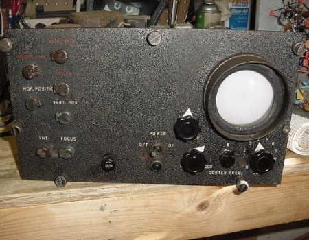
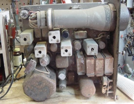
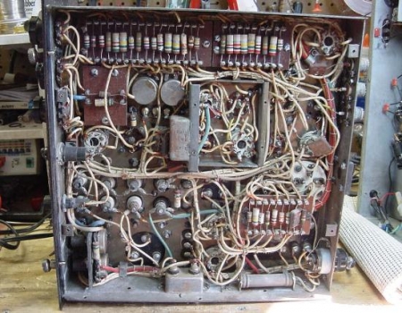
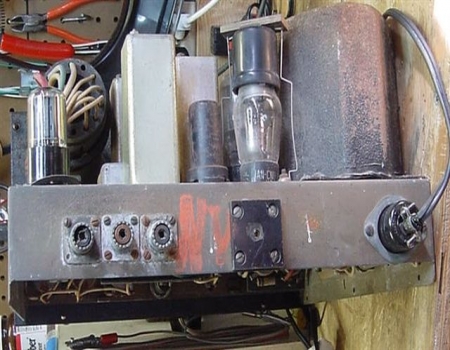
The Panadaptor is designed for operation in conjunction with a receiver to allow the operator a means to visually monitor up to a large portion of the frequency spectrum. The device will allow the operator to visually analyze the characteristics of a transmitted signal such as modulation, distortion, key clicks, carrier shift, parasitic radiations, and other types of transmission parameters. The unit will allow the operator to view both periodic(automobile ignitions, motors, buzzers, etc.) and aperiodic(static crashes) transient disturbances. For the amateur radio operators among us, the panadaptor can also be used to find a clear frequency on a crowded band. With a panadaptor you will be able to see what you are hearing from the receiver. The CRT(Cathode Ray Tube) display on the panadaptor will show a blip in the form of an inverted V on the screen when a signal is present. The size of this blip is determined by not only the strength of the received signal, but also the transmission type. In other words, a SSB(Single Side Band) signal will be a tad smaller then an AM signal. As the receiver is tuned from a low to a high frequency, the signal deflections will move across the display screen from left to right. The unit is designed for use with any superheterodyne receiver that employs an IF(Intermediate Frequency) of between 450 and 470 KHz. If a receiver is used that employs a different IF between 450 and 470 KHz, then the RF bandpass transformers of the panadaptor should be realigned for best performance. In many cases no modifications to the receiver is required. When the panadaptor is connected to a receiver, it will in no way interfere with the normal operation of the receiver. A panadaptor employs an RF input cable that is used for connecting the unit to a companion receiver. The RF cable often terminates in a small loop which is intended to be connected to the plate pin on the converter tube(also known as the mixer or 1st detector) of the receiver. Remember that this connection goes to the B+ line and very bad things will happen if this connection is shorted. At the bottom of this page I list the plate pin number for several popular converter tubes. The RF cable also has an alligator clip that should be connected to the receiver chassis. The word Panadaptor is short for Panoramic Adaptor. Technically, panoramic reception is defined as the simultaneous visual reception of a multiplicity of radio signals over a broad band of frequencies. The panadaptor is a really nifty and powerful piece of equipment that can be used for so much more then simply watching a section of the frequency spectrum. Some other uses of the panadaptor include automatic visual monitoring, automatic aural monitoring, three way QSO's or conversations, spotting replies to your CQ call, watching for CQ calls, finding clear frequencies, locating stations whose frequency is unknown, instantaneous signal strength meter, measuring the percentage of AM modulation, spotting distortion on AM signals, spotting spurious and RF parasitics, detecting splatter, detecting carrier shift and frequency drift, finding key clicks on CW signals, checking deviation of FM signals, identifying AM on FM signals, detecting residual hum on a carrier, frequency measuring and setting, quickly checking a band for activity or propagation, and on and on. Experimental versions of the panadaptor appeared just prior to the outbreak of WWII. Government agencies that relied on standard direction finding techniques for intercept and counter-espionage monitoring quickly learned that it was virtually impossible to follow illegal stations which would change frequencies at random intervals. Panoramic reception solved this problem since they can visually display the signals present on a given portion of the band. Any disappearance and then subsequent reappearance of a suspicious signal on another frequency was immediately detectable. The panadaptor had yet more to offer in the way of direction finding by obtaining null points with greater accuracy which aided in triangulation of the illegal signal. When WWII broke out the panadaptor was pressed into service in great numbers. In the UK there are reports of more then 100 panadaptors at one location operating simultaneously. Panadaptor's were installed at listening posts, control towers, aboard ships and numerous other installations. A spectacular application of the panadaptor was in radar countermeasures. The units would allow the Allied transmitters to match the exact frequency and characteristics of the enemy radar systems for effective jamming techniques. Speaking of radar, the use of pulse automatic gain control, which is used to compress the stronger signals while leaving the weaker signals unaffected, made its appearance in panadaptors long before it was ever incorporated into radar receivers. Panadaptors have been manufactured by numerous companies through-out the years. One of these companies was the Hallicrafters corporation with their SP-44. Today, modern companies such as Icom and Yaesu have this feature built into some of their transceivers. If one wanted this feature in a tube era radio then the Central Electronics 100V and 200V some what come to mind. The panadaptor on this web page is very similar to the BC-1031 series of panadaptors used by the Signal Corps and others. The unit above has an extra control knob though. This extra black control knob is located next to the display and is more toward the center then the rest of the knobs. As can be seen in the photographs above, this unit needs a little TLC and should be a fun project once it gets a turn on the ole workbench. |