AI4FR Virtual Shack Tour 

Hallicrafters Items


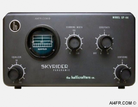
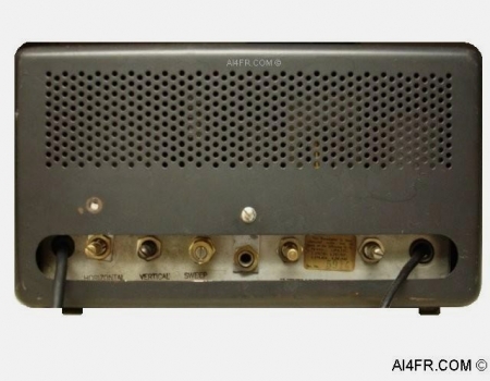
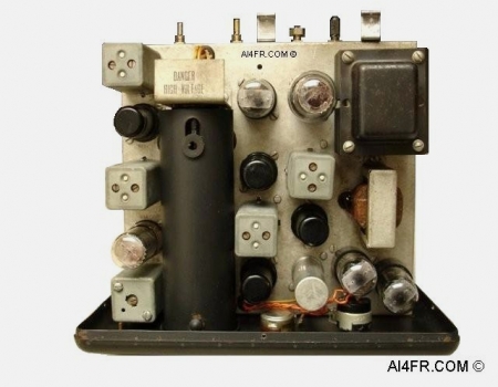
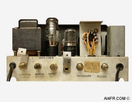
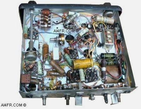
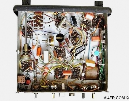
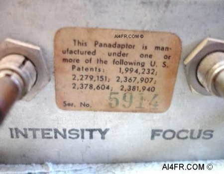
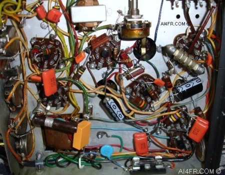
Production Year 1946 at $99.50 

The Hallicrafters Skyrider SP-44 Panoramic is designed for operation in conjunction with a receiver to allow the operator a means to visually monitor up to a 200 KHz wide frequency spectrum. The device will allow the operator to visually analyze the characteristics of a transmitted signal such as modulation, distortion, key clicks, carrier shift, parasitic radiations, and other types of transmission parameters. The unit will allow the operator to view both periodic(automobile ignitions, motors, buzzers, etc.) and aperiodic(static crashes) transient disturbances. For the amateur radio operators among us, the SP-44 can also be used to find a clear frequency on a crowded band. A 1/4 phone jack on the back of the unit allows for audible monitoring of all signals within the 200 KHz range at one time. With the SP-44 you will be able to see what you are hearing from the receiver, and be able to monitor and locate stations up to 100 KHz off to either side of your center frequency. The 2 inch CRT(Cathode Ray Tube) display on the panadaptor will show a blip in the form of an inverted V on the screen when a signal is present. The size of this blip is determined by not only the strength of the received signal, but also the transmission type. In other words, a SSB(Single Side Band) signal will be a tad smaller then an AM signal. As the receiver is tuned from a low to a high frequency, the signal deflections will move across the display screen from left to right.

The SP-44 is designed for use with any superheterodyne receiver that employs an IF(Intermediate Frequency) of between 450 and 470 KHz. The unit has been factory set for a receiver having an IF of 455 KHz. If a receiver is used that employs a different IF between 450 and 470 KHz, then the RF bandpass transformers of the panadaptor should be realigned for best performance. In many cases no modifications to the receiver is required. When the SP-44 is connected to a receiver, it will in no way interfere with the normal operation of the receiver.

The SP-44 is supplied with an RF input cable that is used for connecting the unit to a companion receiver. The RF cable terminates in a small loop which is intended to be connected to the plate pin on the converter tube(also known as the mixer or 1st detector) of the receiver. Remember that this connection goes to the B+ line and very bad things will happen if this connection is shorted. At the bottom of this page I list the plate pin number for several popular converter tubes. The RF cable also has an alligator clip that should be connected to the receiver chassis. If the RF cable on your SP-44 has been terminated with say a coaxial terminal, then it probably has been modified some time in the past for a more permanent installation and operation should not be affected. Whether the RF cable is modified or not, when the panadaptor is connected to some receivers with two or more RF stages, it may not be possible to observe up to the rated 200 KHz of bandwidth. However, the bandwidth may be extended by realigning the RF bandpass transformers of the panadaptor so that the peaking frequencies are less then ± 90 KHz from the receiver IF.  

The SP-44 has been designed for ease of use, all of the controls that are used to operate the unit on a day to day basis are located across the front panel, while the controls that are used to make trace adjustments are located on the rear apron of the chassis. The electronic components of the SP-44 are mounted on a cadmium plated steel chassis which is housed in a metal cabinet with rubber mounting feet. A light shade protrudes out slightly above the CRT display for greater visibility. It is generally a good idea to have the AVC(Automatic Volume Control) of the receiver turned off when using the panadaptor. Otherwise the signal that appears at the center of the display screen may control the height of all of the other signals that are displayed. For example, if the receiver is tuned to a strong signal, the weaker adjacent signals may be reduced in height or they may not appear at all.

Scanning across the front panel from left to right, the controls and their functions are as follows: at the bottom left hand corner is the Equalizer control that was perfected during WWII and is used to compensate for the varying preselector characteristics of the receiver. In the center is the Scanning Width control that adjusts the bandwidth of the SP-44 from zero to 200 KHz. Next is the Sensitivity control knob that has three functions. The first function of the Sensitivity control is as the On/Off switch, next it is used to control the height of the CRT deflections which at the same time controls the audio output when a listening device is connected to the 1/4 inch phone plug on the rear apron of the unit. At the bottom right hand corner is the Centering control knob which aligns the "pip" of the received signal with the zero mark on the display screen of the panadaptor.

The 10 tubes that are used in the SP-44 along with their functions are as follows: 2AP1 = CRT, 6SG7 = RF Amplifier, 6SA7 = Mixer & Oscillator, 6SG7 = IF Amplifier, 6SQ7 = Detector & Video Amplifier, 6AC7 = Reactor, 6SN7 = Saw Tooth Generator and Amplifier, 6X5 = Low Voltage Rectifier, 6X5 = High Voltage Rectifier, and a VR-105 as the Voltage Regulator. The unit requires a 105 to 125 volt, 50 to 60 cycle AC power source. The normal power consumption of the SP-44 is approximately 55 watts. The physical dimensions of this panadaptor is 11 inches wide by 6 3/16 inches high by 10 3/4 inches deep.  

The word Panadaptor is short for Panoramic Adaptor. Technically, panoramic reception is defined as the simultaneous visual reception of a multiplicity of radio signals over a broad band of frequencies. The panadaptor is a really nifty and powerful piece of equipment that can be used for so much more then simply watching a section of the frequency spectrum. Some other uses of the panadaptor include automatic visual monitoring,  automatic aural monitoring, three way QSO's or conversations, spotting replies to your CQ call, watching for CQ calls, finding clear frequencies, locating stations whose frequency is unknown, instantaneous signal strength meter, measuring the percentage of AM modulation, spotting distortion on AM signals, spotting spurious and RF parasitics, detecting splatter, detecting carrier shift and frequency drift, finding key clicks on CW signals, checking deviation of FM signals, identifying AM on FM signals, detecting residual hum on a carrier, frequency measuring and setting, quickly checking a band for activity or propagation, and on and on.  

Experimental versions of the panadaptor appeared just prior to the outbreak of WWII. Government agencies that relied on standard direction finding techniques for intercept and counter-espionage monitoring quickly learned that it was virtually impossible to follow illegal stations which would change frequencies at random intervals. Panoramic reception solved this problem since they can visually display the signals present on a given portion of the band. Any disappearance and then subsequent reappearance of a suspicious signal on another frequency was immediately detectable. The panadaptor had yet more to offer in the way of direction finding by obtaining null points with greater accuracy which aided in triangulation of the illegal signal. When WWII broke out the panadaptor was pressed into service in great numbers. In the UK there are reports of more then 100 panadaptors at one location operating simultaneously. Panadaptor's were installed at listening posts, control towers, aboard ships and numerous other installations. A spectacular application of the panadaptor was in radar countermeasures. The units would allow the Allied transmitters to match the exact frequency and characteristics of the enemy radar systems for effective jamming techniques. Speaking of radar, the use of pulse automatic gain control, which is used to compress the stronger signals while leaving the weaker signals unaffected, made its appearance in panadaptors long before it was ever incorporated into radar receivers.

Panadaptors have been manufactured by numerous companies through-out the years. The model PCA-2 type T-200 was produced by Panoramic Radio Corporation in New York and is nearly identical to this Hallicrafters SP-44.. The main difference between the two is the finish on the cabinet and the style of knobs on the front. Today, modern companies such as Icom and Yaesu have this feature built into some of their transceivers. If one wanted this feature in a tube era radio then the Central Electronics 100V and 200V some what come to mind. Click HERE for a look at a military style of panadaptor.


The photograph on the left is of the top of the Hallicrafters SP-44 with the cabinet removed. This picture displays the tube compliment and some of the other major components that are found on the top of the chassis. A warning has been printed in black ink at the rear of the 2AP1 Cathode Ray Tube(CRT) which states the following "Danger High Voltage".

The photograph on right is a close up of the operator controls that are found on the rear chassis apron. These controls are assessable even with the cover in place. Scanning across the rear from left to right, the controls and their functions are as follows,  at the left is found the Horizontal Position control that is used to position the baseline trace horizontally on the display. Next is the Vertical Position control which is used to position the baseline trace vertically on the display. Next is the Sweep Pad control that is used to obtain a 200 KHz sweep width when the scanning width control on the front panel has been set at maximum. The next item is the 1/4 phone jack that should be used with a listening device that has a high impedance in the order of 500k ohms. Next to this is the Intensity control which is used to adjust the brightness of the trace. At the right is the Focus control which is used to adjust the sharpness of the trace.


The picture on the left is of the Panadaptor in un-restored condition. This Hallicrafters SP-44 has had service work preformed on it in the past. The "bathtub" style of capacitor that is located in the upper right of the photograph is not original. This replacement bathtub capacitor is rated for a whopping 600 volts less than what the circuit requires. The capacitor has a value of .1uf @ 400 volts, and the circuit requires a .1uf @ 1000 volts. I did not have any capacitors on hand that was rated for such a high voltage so I decided to make some. In the text for the pictures below I describe how I accomplished this.

The picture on the right shows the new components installed under the chassis after the restoration work had been completed. Nearly all of the resistors were bad in this unit. Most all of them measured well beyond their rated tolerance level. Many had even doubled in value. I also ran into a wire that was not connected to any thing at one end. Finding loose wires always puts a little fear in me. Why was it disconnected which created a potentially dangerous situation? Did it get so hot that it burned in two? Was it disconnected by a former owner because there is a problem with part of the circuit and now a given function no longer worked? Maybe it was a poor solder connection that created this situation. Luckily, that was not the case and after some research it turns out that the wire was for an old modification that had been reversed by a previous owner.

The little orange things are capacitors and are commonly referred to as "orange drop capacitors". It is often recommended to replace all of the molded paper and waxed paper capacitors in these older tube era items, which has been done for this restoration. The reason being is that over time the old capacitors may start to dry out and become open, shorted or leak which can hurt the performance of the unit and possibly cause serious damage to some of the components.

Also notice that new electrolytic capacitors have been installed as well. They are the bluish/black colored cylinder shaped items in the upper right quadrant. The original electrolytic capacitor has been left in place on the top of the chassis for aesthetic reasons. It is no longer being used in the circuit. Some times when I do these restorations I will drill out the gunk from inside the old original capacitor and stuff the new replacements inside. I normally do this so that the item will keep its original appearance. Capacitors that are made today are not only sturdier and more precise, but are also much smaller. A capacitor from yesteryear that was the size of a roll of quarters is now the size of a pencil eraser today. In most cases, the new replacement capacitors will easily fit inside the body of the old capacitor. Some folks have been known to take this a step further and go so far as as to even stuff both the waxed paper and molded paper capacitors to give the set a museum quality restoration. As an added touch I have installed heat shrink tubing over the bare wire leads on the positive side of the electrolytic capacitors. The heat shrink tubing can be thought of as carpenters caulk, it gives the work a nice and neat appearance. Before I solder any wires or leads to the chassis or to the tube pins, I clean the oxidation and other gunk from the connection point with a Dremel tool using a wire brush attachment.

The picture on the left is of the right side underneath the chassis. I would like to point out a couple of restoration techniques that I used which is shown in this photograph.

The first is the two pairs of orange drop capacitors in the lower right hand corner. You may recall from the text above about the "bathtub" capacitor that was installed by a previous owner which did not have the correct rating. Even what I built and installed is not quite right but should work just fine.

The circuit requires a capacitor with a rating of .1uf @ 1000 volts. I did not have a capacitor with that value in th junk box, but what I did have was a few capacitors that were rated at .25uf @ 630 volts. So I took two of these .25uf @ 630 volts capacitors and ran them in series. Now what that does in theory is double the voltage rating and drop the total capacitance in half. So in theory I now had a .12uf @ 1260 volts(capacitance value is rounded for simplification). This was close enough for me as well as for the circuit requirements. To date, every thing has worked out well and the unit is functioning as it should. But a warning is in order. While in theory this can be done, connecting capacitors in series is not recommended. This is because with a series connection, one capacitor will usually end up getting more voltage than the other. Why you ask? Well, this is because the leakage resistances of the two capacitors are rarely if ever the same. This means that the capacitor with the higher resistance will get a greater amount of the voltage from the circuit which will often result in a series connected capacitor breaking down. Since these capacitors are not electrolytic's, nor are they of a great value in capacitance(which really means nothing) I figured it would be OK. The proper procedure would be to replace the capacitors, or any component for that matter, with a part that has the correct value that the circuit calls for. Not doing so is often asking for trouble.

The second hint has to deal with the yellow and blue capacitors that are shown at the bottom center of the picture. The yellow Y2 capacitor is the rectangular item, while the blue X2 capacitor has a round shape. These are UL rated safety bypass capacitors. They are specially made capacitors that should be installed at the AC input power cord.(the other end plugs into the wall of our homes). The yellow one is a Y2 safety bypass capacitor and it runs from the neutral wire(large slot on the wall outlet) to the ground inside of the electronic circuit. The blue one is called an X2 safety bypass capacitor. This one runs between the neutral and the hot AC input power leads(small slot to large slot on the wall outlet). Should these capacitors ever fail, they are designed to create an open circuit. In other words, if they fail the juice will no longer flow through an items circuitry and the item will no longer function. If a non safety bypass capacitor was used and it failed, it could create a short circuit and possibly cause a fire. Now that we have briefly covered Y2 and X2 capacitors, you might be wondering how you will ever remember which is which and what goes where? The way I keep track of these critters is to think of the letter X as a cross such as in across the line. Thinking of it this way, I am reminded that the X capacitor should be installed across the hot and neutral AC input power wires.

One other thing, the hot wire coming from the wall outlet should first be wired to go to the fuse, then to the AC bypass capacitor, and then to the item's power switch. You may have to do some rewiring to get this done. Often it will be found that the hot lead first goes to the power switch and then to a fuse. Should there ever be a short in the circuit that blows the fuse, the switch and possibly the chassis could still be hot with AC and deliver a potentially fatal shock. With the hot lead running to the fuse first, this deadly situation will be avoided.

The picture on the right is a close up of the sticker that was found on the rear apron of the unit. This sticker shows a number of patents as well as the serial number of this Hallicrafters SP-44 which is 5914.


Plate pin numbers for converter tubes.

As stated in the text at the top of this page, the RF input cable should be connected to the plate pin on the converter tube which is also known as the mixer tube or 1st detector tube in some receivers. That pin number is shown below for several popular converter tube types. These pin numbers corresponds to looking at the bottom of the socket or at the base of the tube. Important, this connection goes to the B+ line and should it become shorted, there is a very good chance that the IF transformer and other components will become damaged in the receiver.

1A7 = pin number 3

6A7 = pin number 2

6A8 = pin number 3

6J8 = pin number 3

6K8 = pin number 3

6L7 = pin number 3

6SA7 = pin number 3

6SB7 = pin number 3

7Q7 = pin number 2

12SA7 = pin number 3


Resources:

Radios by Hallicrafters with Price Guide by Chuck Dachis

Hallicrafters owners manual  

      AI4FR                                                                                                                                                                                                  AI4FR                                                                                                       AI4FR

Trump WON!! Biden CHEATED!!

Avoid the experimental gene therapy C19 DEATH shot!!  

Think Critically!!

Ukraine = Corruption

Was Hitler right?

Copyright © John Whitt 2022 All rights reserved. 

Created with the QTH.com SiteBuilder.