AI4FR Virtual Shack Tour 

SW Receivers


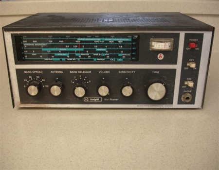
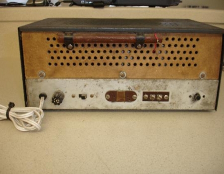
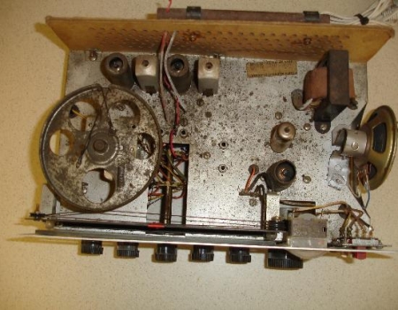
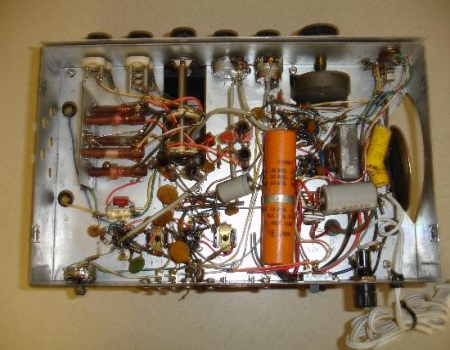
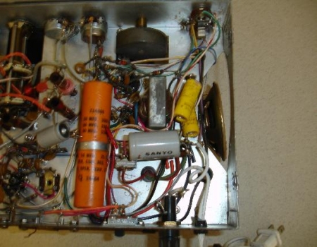
Production Year 1963 - 1972 at $40 to $45

The Allied Knight Star Roamer is a single conversion Super-heterodyne short wave receiver that was produced by Allied Radio in a do-it-yourself kit form.

It uses 4 tubes as follows a 6BE6 as a Converter, 6HR6 as an IF Amplifier, 12AX7 as a  Audio Amplifier and a 6AK6 for the Audio Output. The radio has 5 Bands which included the Sub-Broadcast band of 200kHz. to 400kHz., 550 to 1600 KHz., 1.8 to 4.8 MHz., 5.8 to 12 MHz. and 12 MHz. to 30 MHz.

The controls on the front are as follows and starting on the left, a Bandspread that is numbered 0 to 100, Antenna Trimmer, Band Select, Volume control, Sensitivity and a Tuning knob. On the right of the radio there are three switches and starting at the top they are as follows, an On/Off Power switch, AVC switch and a ANL switch.

The radio utilizes a built in speaker. On the front there is a standard 1/4 inch connection for headphones. This receiver also has a built-in Medium Wave(broadcast band) Ferrite antenna and a CW practice jack, both of which are located on the back.

The power requirement is 110 to 130 volts AC at 60 Hz. The tuning of CW/SSB was made possible by carefully adjusting the sensitivity control.

At one time this was a very popular and affordable receiver kit that was sold in large numbers.


These next two photographs show the top and one side of the Knight Star Roamer receiver. As can be seen, this radio will will need some TLC but enough of it is there to make for a fun project. The photograph on the right shows the vent holes for the built in speaker.

The photograph on the left is of the inside with the case removed and shows that there is plenty of room to move around. One thing that I did find interesting with this receiver is the position of the air variable capacitor. Notice the large round tuning wheel that sits on the front of this capacitors. This one is mounted in a horizontal position which means that the air variable capacitor is mounted in a vertical position. As can be seen in these pictures, they were taken before any restoration process had begun. The photograph on the right is a picture of under the chassis. I have a feeling that many of the electrolytic capacitors seen here did not originally come with the kit.


In the photograph on the left we see a close up of the large round tuning wheel that was described above. Here we can really see how dirty and grungy this receiver is. The photograph on the right is a close up of under the chassis. While the original builder of this kit did an outstanding job, that statement can not apply to the many repairs this receiver has gone through.

      AI4FR                                                                                                                                                                                                  AI4FR                                                                                                       AI4FR

Trump WON!! Biden CHEATED!!

Avoid the experimental gene therapy C19 DEATH shot!!  

Think Critically!!

Ukraine = Corruption

Was Hitler right?

Copyright © John Whitt 2022 All rights reserved. 

Created with the QTH.com SiteBuilder.