AI4FR Virtual Shack Tour 

Hallicrafters Items


Production Year 1950 - 1951 at $89.95 

The Hallicrafters S-77 is a Single Conversion, Superheterodyne, general coverage receiver that is used for the reception of AM and CW signals. The receiver incorporates 8 tubes in its circuit and has four bands with continuous coverage from 540 KHz to 44 MHz. The first band covers from 540 KHz to 1680 KHz, the second band covers from 1.68 MHz to 5.4 MHz, the third band covers from 5.3 MHz to 15.5 MHz, and the fourth band covers from 15.5 MHz all the way up to 44 MHz. The Intermediate Frequency(IF) of this receiver is 455 KHz. The internal front panel mounted speaker is of the permanent magnet moving coil design that measures five inches across and has a voice coil impedance of 3.2 ohms. Received signals exit through a perforated section on the front of the unit. If headphones are to be used, the receiver requires a set with a low impedance. Besides listing the frequencies, the analog frequency display has been calibrated at the top of the dial from 0 to 100 and is used in conjunction with the smaller Bandspread scale which is also calibrated from 0 to 100. This type of calibrated system aids in accurate logging and quick re-tuning of the receiver. This radio uses the standard #47 bulb for the dial lamp and is housed in a sturdy metal cabinet..

The Hallicrafters S-77 also features band spread tuning. The band spread dial is located to the right of the larger main tuning dial and is calibrated from 0 to 100. To operate the band spread dial, set the main tuning dial to the high frequency limit of the range of frequencies to be covered and then tune stations in with the band spread control. For example: say that the 40 meter amateur band is to be covered. Set the main tuning dial pointer to 7.3 MHz and tune in the stations with the band spread control. The band spread control allows for fine tuning of stations and forces the operator to move across the frequency spectrum at a much slower pace, thus helping to insure that weak stations are not missed. Tuning the bandspread control from 0 to 100 tunes the receiver progressively lower in frequency. One thing to keep in mind is that the calibration of the main tuning dial will only be correct when the band spread dial is set to zero.

The front panel controls consume the entire bottom edge of the face of this receiver. Scanning across the front panel from left to right, the operator controls and their functions are as follows: a Sensitivity control which is the same thing as a Radio Frequency(RF) gain control, and is used to adjust the sensitivity of the receiver. Next is a 4 position Band selector knob that is used to select one of the four bands for reception. The last operator control on the left hand side is the Volume control knob. Often times the power switch and the volume setting are on the same front panel control knob. Having these two controls on separate knobs can be very convenient. Once the power is turned on to the receiver, and assuming it had already been previously set on a favorite station, the operator can now walk away. When the receiver warms up, it will be at a comfortable listening level for the operator and there will be no need to return to the radio to re-adjust this setting.

At this point we have made it to the center of the receiver and run into the first of the four front panel switches. This first switch on the left is used to turn On and Off the Automatic Volume Control(AVC). This switch in most cases is preferably on when the operator is receiving phone or AM signals. With the switch in the off position, the operator should control the RF gain of the receiver with the sensitivity control, otherwise the receiver will block or overload on strong stations. The next switch is used to select the desired receiving mode and is labeled C.W. on the left and A.M. on the right. The last switch in the center of the receiver enables the operator to turn on or off the Noise Limiter circuit which is used in an attempt  to clip the noise voltage peaks generated by automotive and other electrical disturbances. Moving upwards, the large knob in the center on the left is the Main Tuning control and the one on the right is the Bandspread control.

The operator controls on the right start with a knob that has two functions. This control is used to turn On or Off the Power to the receiver and its second function is used to adjust the Tone of the received audio signal. The last knob that we come to is the Pitch control which allows the operator to change the pitch of the received CW signal. We now run into the last of the four front panel switches which is labeled as the Send/Receive switch. This switch is used when the S-77 is paired up with a transmitter. The Send/Receive switch removes the plate voltage from the tubes of the S-77 which makes the receiver inoperative during times of transmission. This switch can also be used to conserve power during a stand-by period when it would be important to have the radio spring to life with just a flick of a switch instead of having to wait for the tubes to warm up. Lastly at the bottom right hand corner of the front panel is a 1/4 inch headphone jack.

The 8 tubes that are used in this receiver along with their functions are as follows, 25Z6 = Rectifier, 25L6 = Audio Output, 6SC7 = 1st Audio Amplifier & BFO, 6H6 = Detector & ANL, 6SK7 = 1st IF Amplifier, 6SK7 = 2nd IF Amplifier, 6SA7 = Converter, and a 6SG7 as an RF Amplifier. The power source requirements are 105 to 125 volts DC or between the same voltage range but with 60 cycles AC. A Ballast resistor R-38 is used for 105 to 125 volt operation. The receiver can also operate from 210 to 250 volts DC or between the same voltage range but with 60 cycles AC. When the receiver is operated from a 210 to 250 volt power source the ballast resistor R-39 should be used. The normal power consumption of the receiver is 40 watts. The physical dimensions of the radio are 18.5 inches wide by 9.1 inches high by 9.8 inches deep.

The photograph on the right is of the back of the receiver. The connections and such found here are as follows, an AC/DC power cord on the left, and at the right is a 3 terminal antenna strip. The 3 terminal antenna strip is marked "A1", "A2" and "G" and known as Antenna 1, Antenna 2 and Ground. A jumper bar consisting of a strand of wire is normally connected between terminals "A2" and "G" for single wire antenna systems as well as unbalanced antenna transmissions lines. For a doublet antenna system with a balanced transmission line, the jumper between "A2" and "G" would be disconnected. If a concentric transmission line(coaxial cable) with a grounded outer conductor is used, connect the inner conductor to terminal "A1" and the outer conductor to "A2" followed by a jumper wire between terminals "A2" and "G". The station ground connection is to be connected to the "G" terminal. 

The Hallicrafters company manufactured an "A" version known as the S-77A from 1952 through 1955. The $89.95 price tag was kept the same for the consumer. The main difference between the two receivers was some of the values on the components had changed. Each version of the model S-77 receiver is identical in both function and in appearance to the Hallicrafters S-40B except for the internal AC power supply circuity that is used on the S-40B. The Hallicrafters S-40B also had a slightly different tube compliment and used a 5Y3GT as the rectifier, and a 6K6GT for the audio output. An interesting note is that on the top of the chassis on the S-77 that is featured on this web page has been factory stamped 5Y3GT next to the 25Z6 tube socket.


The photograph on the left is of the top of the S-77 with the hinged cover in the open position. This picture displays the tube compliment and some of the other major components that are found on the top of the chassis. Notice also the green #47 dial lamps that I installed which gives the receiver a nice outward appearance while in operation. The original dial lamps were clear. The green bulbs help to enhance the color of the original green dials. The red and black power wires going to the dial lamps is not original and were replaced when I did the restoration on this receiver.

The photograph on the right is a peek under the chassis with the bottom cover removed. The yellow electrolytic capacitors are not original and were installed by a previous owner some time in the distant past history of this receiver.  

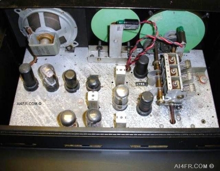
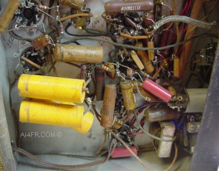
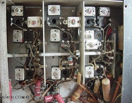
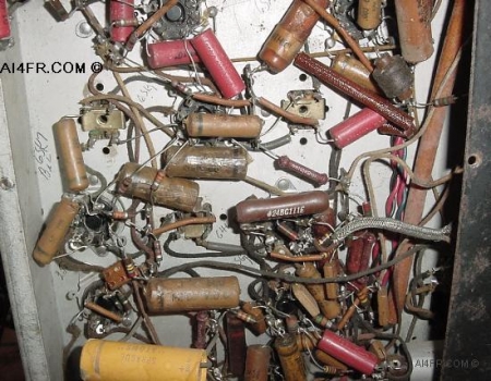
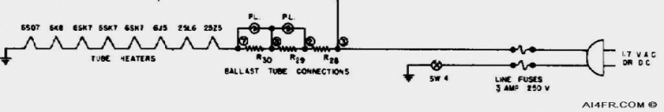
These next two pictures were taken before any work was preformed on this receiver. They show the components that were found underneath the chassis. This Hallicrafters S-77 was just slap full of cobwebs and insect remains. It must have sat on a shelf or up in an attic for many years before it found its way here.

The photograph on the left is of the RF deck. The picture on the right displays many of the waxed paper and molded paper capacitors that make up the circuitry of the S-77. These capacitors are often found to be the source of trouble. It is usually recommended that all of these capacitors along with the electrolytic capacitors be replaced. The reason being is that over time the old capacitors may start to dry out and become open, shorted or leak which can hurt the performance of the receiver and possibly cause serious damage to some of the major components. Some times when I do these restorations I actually drill out the gunk from inside of the old electrolytic capacitor and stuff the new replacements inside. I normally do this so that the radio would keep its original appearance. Capacitors that are made today are not only sturdier and more precise, but are also much smaller. A capacitor from yesteryear that was the size of a roll of quarters is now the size of a pencil eraser today. In most cases, the new replacement capacitors will easily fit inside the body of the old capacitor. Some folks have been known to take this a step further and go so far as as to even stuff both the waxed paper and molded paper capacitors to give the set a museum quality restoration. Before I solder any wires or leads to the chassis or to the tube pins, I clean the oxidation and other gunk from the connection point with a Dremel tool using a wire brush attachment.   


ALIGNMENT PROCEDURE:

In order to do an alignment on this receiver the technician will need just a few basic service tools. These items include a signal generator which must cover the frequency range of the S-77 including 455 KHz, a non-metallic screw driver and a standard RMA(Radio Manufacturers Association) dummy antenna. The RMA dummy antenna consists of a 0.0002 MFd capacitor that is in series with a 20 uH RF choke. The choke or inductor is shunted by a .0004 MFd capacitor in series with a 400 ohm non-inductive resistor. The RMA antenna sounds more complicated then it really is. Please click on RMA Schematic for details on this antenna and why it should be used.

The first step in the alignment procedure is to turn on the receiver and the signal generator and allow each of them to warn up and stabilized. Around a half an hour will often suffice. The next step is the proper setting of the controls on the front of this receiver. Set each of the controls as follows, sensitivity and volume is set at maximum, the AVC and Noise Limiter is turned off, bandspread at zero, CW/AM is set to AM, standby/receive is set on receive, and the tone control is set on high.

There are normally at least two alignments that must be preformed on a receiver. It is important to always do the IF alignment first and the RF alignment last. This receiver is no different and the IF alignment is preformed first. The IF of this receiver is 455 KHz. The chassis will need to be removed from the cabinet to preform the IF alignment. The RF alignment is just the opposite and should be done with the chassis installed inside of the cabinet. Access to preform the alignment is done through holes in the bottom of the cabinet. The reason it is done this way is because the calibration of the oscillator will be slightly effected by changes in the capacity between the cabinet bottom and the RF coils and wiring.

With all that done lets begin. The receiver should be set to band one and the dial set on 1 MHz. Tune the signal generator for a 455 KHz modulated signal and connect the positive lead to the stator plates in the center of the tuning gang and the negative lead to the chassis. Adjust coils A through F for the loudest audio from the speaker of the receiver. Adjustment points B, D and F are made from the top, while the rest are accomplished through the bottom of the cabinet.

For the next step we now need to set the signal generator to produce a 455 KHz unmodulated signal and set the AM/CW switch to the CW position. All of the other settings are the same as above. Once done, remove the pitch control knob from the front of the receiver and adjust point G which is the shaft from the pitch control for a zero beat. Once done, replace the knob but be sure to put the dot on the knob in the center position of the tuning range of the pitch control.

The RF alignment is just as easy but a touch more tedious. It involves changing the frequency of the receiver for each band and matching this frequency with the signal generator. There will be a total of eight frequency changes that will need to be made, two for each band. One thing to keep in mind is that it is some times helpful to run through each band a second time for a final tweaking which will yield superior receiver performance before moving on to the next band.  

Lets begin, receiver functions should be set as described above. Connect the RMA dummy antenna to terminal A1 and make sure that there is a jumper between A2 and G. The ground lead from the signal generator is connected to the chassis. Set the band switch to four and tune the receiver and signal generator(modulated) to 36 MHz. Now adjust points H, I and J located on the bottom of the receiver for the loudest audio from the receiver's speaker. Once done, tune the receiver and signal generator to 18 MHz and adjust points K, L and M located on the bottom of the receiver for the loudest speaker audio.

Now we move to band three and tune both the receiver and signal generator to 14 MHz. Next we adjust points N, O and P on the bottom of the receiver for the loudest speaker audio. Now we move to the other side of the dial and adjust both the receiver and signal generator to 10 MHz and adjust points Q, R, and S which are also located on the bottom of the receiver for the loudest speaker audio.

Moving right along we now set the receiver to band two and adjust it and the signal generator to 5 MHz. Once done we adjust points T, U, and V which are found on the bottom of the receiver for the loudest audio from the receivers speaker. Once done, we next set both the receiver and signal generator to 1.8 MHz and adjust point W that is found on the bottom of the receiver for the loudest speaker audio.

The last two steps in our RF alignment takes us to band one. Tune both the receiver and signal generator to 1.5 MHz and adjust points X, Y, and Z that are found on the bottom of the receiver for the loudest speaker audio. Are you ready to finish this job? Excellent, tune both the receiver and signal generator to 600 KHz and adjust point Z which is found on the bottom of the receiver for the loudest audio from the receiver's speaker. That's it, you are now done. Did you notice how the adjustments followed the alphabet?

All of the adjustments above will need to be done with the non-metallic screw driver. For safety reasons, do not preform this work alone or if you are tired. It is not worth your life.


WARNING!! In the AC/DC receivers such as the one featured on this page, the chassis and cabinet are normally at the same potential. In later years, some manufacturers attempted to isolate the chassis from the cabinet with insulators. It is very important that you do not rely on these insulators a half a century later. A lot could go wrong such as, are they still in good condition, did a previous owner reassemble the radio properly, and so on. Depending on which way the power cord is plugged into the wall can put the entire receiver at 120 volts above ground. This means that if the operator has one body part resting on an earth ground and reaches over and touches an exposed part of the receiver, the operator can receive a potentially fatal shock.

The partial schematic above is for the Hallicrafters S-22R receiver. This schematic would feel right at home with many of the AC/DC receivers, or numerous other electronic items that are built this way. There is no power supply transformer in the circuit of these items which makes them dangerous if the operator becomes careless. Actually, the reason the set can run from a DC power source is because there is no transformer. Today, an item built this way and with a metal cabinet would never get past the Underwriters Laboratory(UL). In fact, if you were to take a survey of the electrical items in your house, what you will most likely find is that just about every appliance with a metal case has a three prong power cord attached to it. As seen in the schematic above, the item will work no matter which way it is plugged into the wall. One way allows the chassis to be connected to the hot wire in the home wiring, while flipping the plug the other way connects the chassis to the neutral side of the house wiring. Either way can be dangerous as both the hot and the neutral house wires in the U.S. carry current. Even though at the fuse panel both the neutral and ground wires go to the same place.

Picture this, the receiver cabinet is hot with 120 volts of AC. You have a hand resting on a desk lamp that uses an older non-polarized power cord or is grounded by a newer 3 prong plug, or your hand is resting on the station ground, or your feet are propped up on the heater, or a thousand other possible ways you could easily be at ground potential, now you reach for a switch on this radio and ZAP, the current runs through your body as it makes its way to ground and kills you. Now your wife becomes a widow and we see your stuff listed at auction under the title "From the estate of a SK". I realize that this sounds harsh, but in most cases there are no second chances. What's that I hear you say? You fully understand the dangers and will watch out for this? What about a family member when you are not home? Do they also understand the danger? Do not risk it. Explain the dangers to them and check the voltage on the chassis with your VOM with the on/off switch in both positions. An isolation transformer can also be used, or better yet, unplug the device when you are away.


Resources:

Radios by Hallicrafters with Price Guide by Chuck Dachis

Hallicrafters owners manual

Sam's photofacts by Howard W. Sams & Co., Inc.  

      AI4FR                                                                                                                                                                                                  AI4FR                                                                                                       AI4FR

Trump WON!! Biden CHEATED!!

Avoid the experimental gene therapy C19 DEATH shot!!  

Think Critically!!

Ukraine = Corruption

Was Hitler right?

Copyright © John Whitt 2022 All rights reserved. 

Created with the QTH.com SiteBuilder.