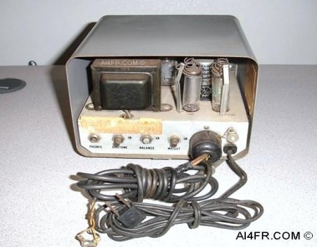
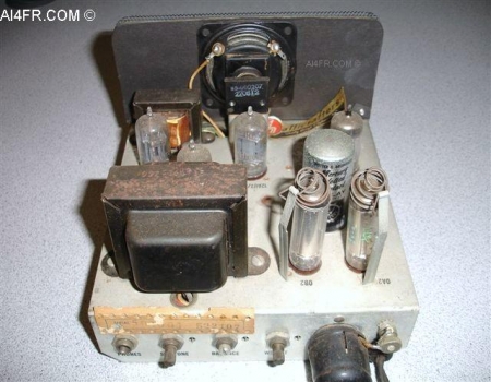
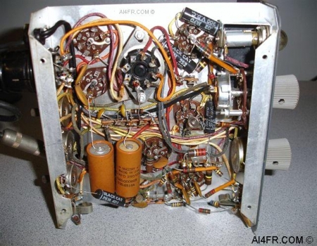
These next two photographs show the Hallicrafters HA-1 keyer with the cabinet removed. The photograph on the left displays the tube compliment and some of the other major components that are found on the top of the chassis, while the picture on the right shows the smaller components that are found underneath. In general, the keyer forms the dots and dashes by the use of digital circuitry and logical sequencing. Both the speed and the mark-space ratios are established by a keyed multi-vibrator that operates continuously as dots and dashes are keyed to form letters. Dashes are formed by adding the output of the time base dot generator with the output from a scale-of-two circuit. Once the dashes are formed, they are always at the correct speed and mark-space ratios. A much more in depth description of the HA-1 circuitry has been detailed below. The 12AU7A tube(V1) is used as a free running astable multivibrator which is keyed by the series triode portion of tube V2A, which is a 12AU7A tube. The positive feedback from the plate of V1A is fed through resistor R16 which holds V2A conducting after a momentary contact of the CW key has been pressed to produce self-completing dots. The dots are uniform whether momentarily initiated or fully keyed, as in a series of dots. The speed is controlled by a positive grid bias adjustment from the R9 potentiometer. The speed range is determined by the selection of grid return resistors R1 and R6, or R2 and R7. The mark-space ratio is adjusted by a differential grid resistor R8, with no effect upon speed. Tube V3 which is a 12AU7A tube is triggered as a bistable multivibrator, or a scale-of-two circuit. When keyed by the series triode tube V2B(12AU7A), tube V3 may be triggered by a negative pulse formed at the start of a dot from the plate of tube V1B. When it is so triggered, the plate of V3B will flip and remain positive until another negative pulse is received. Operating in this manner, it forms half-speed dots which are added to the output of V1 and drive the relay tube V4A(12AU7A) to form the dashes. The sidetone signal is produced by a neon-type relaxation audio oscillator which is amplified by V4B, and keyed by the relay. Frequency of the tone is determined by resistor R27 and capacitor C8. The sidetone level is controlled by potentiometer R28. The power supply incorporates an electrostatically shielded transformer to minimize any possible RF pickup and to provide complete isolation from the power line. Silicon rectifiers are used, and tubes V5(OA2) and V6(OB2) provide complete voltage regulation. With some understanding of the basic circuitry under our belt, lets walk through how the self-completing dot is formed. When the CW key lever closes the contact momentarily to form the dot, the grid bias is removed from tube V2A and it starts to conduct. The multivibrator V1 goes into action and causes the plate portion of V1 which is known as V1A to flip positive which allows the electrons to move through resistor R16 and keep tube V2A conducting to form a self-completing dot. The output from the plate of V1A is now applied through resistor R15 and to the grid of triode V4A which conducts and energizes the relay and a dot is formed. Now lets walk through how the self-completing dash is formed which is a touch more involved. When the CW key lever closes the contact momentarily to form a dash, tube V2B starts to conducts to "arm" V3 for triggering. At the same instance, diode CR1 conducts to start a self-completing DOT(not dash). Now the same procedure from above begins. The grid bias is removed from tube V2A and it starts to conduct. The multivibrator V1 goes into action and causes the plate portion of VI which is known as V1A to flip positive which allows the electrons to move through resistor R16 and keep tube V2A conducting to form a self-completing dot. The output from the plate of V1A is now applied through resistor R15 and to the grid of triode V4A which conducts and energizes the relay. The leading edge of the negative-going dot from the plate of V1B moves through the differentiator capacitor C3 and resistor R12 to form a negative pulse which triggers tube V3. The plate of tube V3B then flips positive and thus keying tube V1 through diode CR1, until the leading edge of the second dot provides another negative pulse to flip it back negative. The second dot which has already been initiated, goes through completion to end the dash cycle. At which point the plate voltage of tube V1A moves through resistor R15, and the plate voltage of tube V3B moves through resistor R14 to drive the grid of tube V4A positive. When the plate of tube V4A is in a positive state, it conducts and energizes the relay for a self-completing dash. A couple of final notes on the HA-1 keyer that I would like to discuss has to do with the rating of the mercury-wetted relay contact. The relay is the heart of the keyer so this is an important consideration to keep in mind. The relay contact is rated at 5 amperes maximum, or 500 volts maximum. The product of these two ratings is not to exceed 250 volt amperes, otherwise the contacts on the relay may become damaged. For example, the maximum allowable voltage with a 5 ampere load is 50 volts(5A x 50v = 250 VA). The maximum allowable current with a 500 volt supply is 0.5 ampere(500 V x 0.5 A = 250 VA). Another consideration is that except for very light loads under 2 MA and 50 volts, the relay must be provided with a contact protection network consisting of a capacitor and a resistor in series. When the keyer is used with most Hallicrafters transmitters and transceivers, no protection network is required. Mercury wetted relay part numbers and sources: The notes and research below is from N6IDL and is corrent as of June 2019. Surplus Sales of Nebraska sells a Mercury wetted relay that is supposed to be compatible. It was made by western electric and is much cheaper than e-Bay prices. Surplus Sales of Nebraska, on there web site, indicates that they have a direct replacement for the relay used in the Hallicrafters HA-1 Electronic Key. Surplus Sales of Nebraska's part number is (KO)275B. The Western Electric part number is 275B. Surplus sales of Nebraska is selling them for $10.00 each, $8.00 each if you buy five or more. They are also Listed as: Mercury wetted reed relay, Western Electric DPDT 8 Pin Octal Base. 4200 Ohm coil.(KO)275B Hallicrafter used the following relays in its keyer. JM1-119-11 Potter-BrumfieldHG-1002 C.P. ClareMW1602-4 A.D. LakeMC-23-A1 Aut Eleec Coil resistance = 4000 Ohms, Coil has 23400 turns, Must operate current = 8.1 milliamperes Max Voltage (Coil) 89.5 VDC A special thanks to Steve Fitzgerald(N4KQR) who personally hand delivered this item. Resources: Radios by Hallicrafters with Price Guide by Chuck Dachis Hallicrafters owners manual |