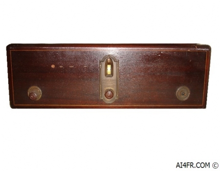
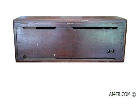
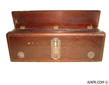
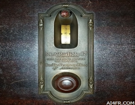
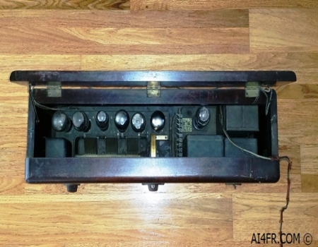
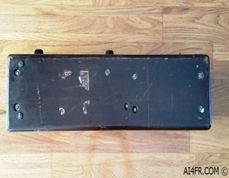
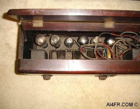
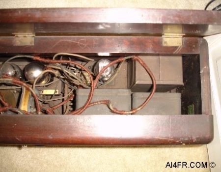
Production year 1927 at $130 with-out tubes. The Radiola 17 was produced by the Radio Corporation of America(RCA) as their first radio designed to operate on 105 to 125 volts AC wall current rather than by battery power. The Radiola 17 is only capable of receiving the AM broadcast band. The radio is a tad heavy and is housed in a rectangular shaped cabinet. The cabinet top, bottom and sides are made from solid mahogany. While the front and back panels are made from veneered plywood. Like many of the broadcast band receivers from this era, it is rather simple to operate with only three operator controls on the front consisting of a volume control on the left, tuning control in the center, and an On/Off power switch located on the right. The tuning indicator does not display the frequency but rather is calibrated from 0 to 100. From my research on this receiver, it appears that RCA produced around 200,000 of these radios. The Radiola 17 circuit is of the TRF(Tuned Radio Frequency) design and is comprised of 3 tuned AM circuits. An external loudspeaker or headphones is required for operation as the set does not have an internal speaker. The Radiola 17 service notes states that the receiver utilizes an output transformer so there is no polarity to the output current of the receiver. The RCA service notes go on to state that one should connect the speaker or cone "in the manner that gives the most pleasing reproduction." The photograph on the right is of the rear panel. The headphone or speaker connections are the two small round holes located on the bottom right corner. The power cord exits from the bottom left corner. This receiver has seven tubes consisting of four UX226's, UY227, UX171A, and a UX280. RCA refers to their tubes as "Radiotrons". One UX226 is used for untuned Radio Frequency(RF) amplification and is coupled directly to the antenna and ground. The second UX226 is used for the first stage of tuned R. F. amplification employing a grid resistance to prevent oscillation and is tuned by the first gang section of the variable condenser. The third UX226 is for the second stage of tuned R.F. amplification and also employs a grid resistance for the purpose of stabilizing or preventing self-oscillation and is tuned by the second gang section of the main tuning variable condenser. The fourth UX226 is for the first stage of audio frequency amplification. The UX171A is employed as the second stage of audio frequency amplification. The UY227 is the detector and is tuned by the third section of the variable condenser. The UX280 is the full wave rectifier that converts the AC wall current to DC. The TRF(Tuned Radio Frequency) receiver design was patented in 1916 by Ernst Alexanderson. This design is usually found composed of several tuned RF(Radio Frequency) amplifier stages followed by additional circuits in which to detect and then amplify the audio signal. The RF amplifier stage amplifies the incoming signal of the desired station while rejecting the other signals received by the antenna. Next the detector circuitry extracts the audio signal from the received radio carrier signal. Next one or more audio amplifier stages increases the power of the audio signal thus making it possible to drive a loudspeaker. Some TRF designs may not have an audio amplifier stage as these receivers were designed to operate with headphones instead of a speaker. The TRF circuit design was quite common in the 1920s. The TRF receiver design is different than the superheterodyne design in use today and is more difficult to keep properly tuned and operating. Each of the tuned circuits in a TRF receiver will need to track to keep the narrow bandwidth tuning. Or said another way, each stage of the receiver must be individually tuned to the frequency of the desired station. Keeping these numerous circuits aligned is difficult. The thought behind this design was that each stage of the receiver would amplify just the desired signal while reducing the signal strength of near-by or interfering stations. This receiver design was eventually phased out and later replaced by the superheterodyne receiver that was invented by Edwin Armstrong in 1918 and is still in use today. The superheterodyne receiver simply requires the operator to tune the receivers' front end by using a single control knob set to the desired frequency while the following stages of the receiver operate at a fixed frequency that never changes. Although the TRF design was phased out decades ago in favor of the superheterodyne design, the TRF was resurrected in 1972 with the introduction of the ZN414 by Ferranti which placed the TRF radio receiver design on an integrated circuit. By using the TRF circuit design it allowed nearly an entire radio to be fitted into one small three pin package. |