AI4FR Virtual Shack Tour 

Broadcast band Receivers


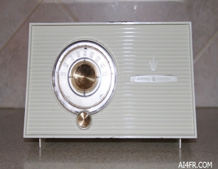
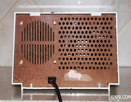
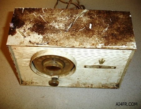
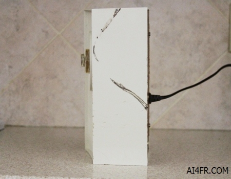
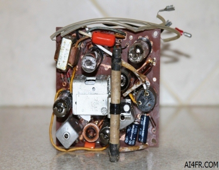
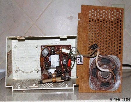
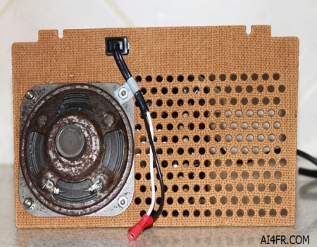
Production year 1956 thru 1958

The General Electric model 876 is a Super Heterodyne receiver that covers the AM Broadcast band from 540kHz to 1600kHz. The IF(Intermediate Frequency) on this receiver is 455kHz and the circuit incorporates two AF(Audio Frequency) stages. This radio utilizes 5 tubes which are 12AV6, 12BA6, 12AU6, 35W4, and a 50C5. The model 876 is housed in a plastic case. This radio has a built in Permanent Magnet Dynamic speaker and a ferrite rod antenna that is attached to the circuit board. The power source can be AC or DC from 105 to 120 volts with either 50 or 60 cycles according to the sticker on the inside of the cabinet. Power consumption is 30 watts. The size of the radio is 10 1/2 inches long by 6 1/2 inches high by 5 inches deep.

This is a simple and basic broadcast band receiver that incorporates three controls which are on the front of the radio. The small knob located under the large dial is an on/off and volume control. The operator would pull this knob to turn on the radio and push it back in to turn it off. Rotating this knob to the left and right decreases and increases the audio level(Volume). The nice thing here when compared to on/off/volume controls in other receivers that must be turned toward the right to both turn on the set and adjust the volume level is that once the audio level is set for the operator's comfort he simply pulls the knob to turn on the radio the next time he wishes to use it and can walk away with no need to return to the set to adjust the volume level once the tubes are warmed up and the set playing. The audio level will be the same as when the set was last used.

The large round knob located directly above the on/off/volume control is for tuning. While the radio can receive from 540 kHz to 1600 kHz the numbers marked on the radio start at 550 kHz and go to 1600 kHz. Marked on the dial is a black triangle which indicates where the radio is tuned in relation to these frequency numbers. The operator simply turns this dial to the left or right to receive stations.

Also marked underneath the dial is a small white triangle marked CD. Marked on the radio a few inches below the broadcast band numbers is two white triangles.

I believe these two CD markings indicate Civil Defense and show this receivers past history from the cold war days. When tuned to either of these two dial settings by lining up the two triangles(one on the dial and either one marked on the receiver) the operator could quickly receive information about an emergency. Civil Defense was used before the foundation of FEMA and Comprehensive Emergency Management. Civil defense was an effort to prepare civilians for military attack. It uses the principles of emergency operations: prevention, mitigation, preparation, response, or emergency evacuation, and recovery. Programs of this sort were initially discussed at least as early as the 1920's but only became widespread after the threat of nuclear weapons was realized. Since the end of the Cold War, the focus of civil defense has largely shifted away from military attack to national and local emergencies and disasters. The new concept is described by a number of terms, each of which has its own specific shade of meaning, such as crisis management, emergency management, emergency preparedness, contingency planning, emergency services, and civil protection.

The two pictures above were taken after the restoration was complete. In the photograph on the right both the black power cord and the four brass machine screws that hold the speaker to the back cover is not original. The speaker was originally held on with pop rivets and the power cord was white.

Other models of this radio which incorporate the same design except for the cabinet color are as follows: model 875 which has a mahogany cabinet and the model 877 which has a pink cabinet. 

The super-heterodyne circuit was invented by Edwin Armstrong in 1918. The circuit of a super-heterodyne(superhet) receiver employs the mixing of signals which provides superior selectivity, frequency stability, and sensitivity when compared with simpler designs such as regenerative, Tuned Radio Frequency(TRF) or Neutrodyne receiver circuits. The superhet, which is still in use today, mixes the received signal with that of an internally produced signal referred to as the intermediate frequency(IF) which allows the receiver to more conveniently process the received radio signal.

The detector, intermediate amplifier, and a-f amplifier of a superhet receiver are actually equivalent to a complete TRF receiver by themselves. The main difference from complete Amplitude Modulation(AM) TRF receiver circuits are that the IF section of a superhet is fixed tuned that is, the resonance is set at one frequency and reception is possible only with signals of the intermediate frequency. The diode detector used in a superhet is somewhat less sensitive than the types used in TRF receivers such as grid leak, square law, linear plate, and similar types.

The signal from the antenna is filtered to reject most of the undesired frequencies and eventually amplified. A local oscillator inside the receiver produces a sine wave(usually 455Kc) that mixes with the received and filtered signal and thus shifting it to a specific intermediate frequency(IF). This IF signal is then filtered and amplified and depending on the circuit it can be further processed in additional ways. Next the demodulator takes this IF signal and demodulates it to recreate a copy of the original information sent in the transmitted radio signal. There are several different superhet circuit designs such as single, double, and triple, conversion.

The word Superheterodyne is a contraction of the words supersonic and heterodyne. In this case the word supersonic(super) indicates those frequencies that are above the range of human hearing. The word heterodyne is derived from the Greek roots where hetero indicates different, and dyne indicates power. Putting all this together superheterodyne simply means frequencies that are above human hearing with a different power.  


The photograph on the left is of the front of the radio showing what it looked like before restoration. The photograph on the right is of the back of the radio. Yes, this radio was a prime candidate for the scrape heap. It certainly took more trouble then what it is worth to get this radio operational. I knew that going in and just felt sorry for the poor thing.

The photograph on the left is a picture of the top of the plastic case before any cleaning or restoration was attempted. Yuck, what a mess. This radio was found in a wood shed with all doors and windows gone. It had been exposed to the elements for many years.

The photograph on the right is a picture of the top of the radio after a lot of elbow grease(cleaning) was applied. The black lines on top of the radio appear to be from where a power cord or some wire became very hot. So hot in fact that it melted an impression on the top of the cabinet. This mark can also be seen in the picture on the left. The original power cord showed no signs of such heating.  

The photograph on the left is of the inside of the receiver before any restoration work was preformed. Some one had swapped out some parts at some point in the past history of this radio. That orange item on the circuit board is a capacitor from modern times of 20 or 30 years ago.

The photograph on the right is a close up of the components on the circuit board after the restoration was completed. The large electrolytic capacitors and one smaller wax paper capacitor was replaced. Several resistors were way out of tolerance so I replaced them as well. The plastic strap that held the ferrite rod antenna in place fell apart and was replaced as well.

The power cord was in need of replacing as well but the question arose on how to do it. Notice the large white plug on the brown backing for the radio in the picture on the left. The brown back has a large rectangle cut out for this white plug which is connected to the power cord. The white plug mates with a plug from the circuit board to supply the radio with power. I thought about splicing into the original power cord if I could find an undamaged section in order to keep the white plug in place. But how long would this last and would it be safe in a year from now when parts of the power cord were not safe now? I thought about fabricating a rectangle piece to cover the slot but how could I attach it to the brown back with out drilling holes? There may have been enough room to sandwich the brown radio back between two rectangular pieces while using small machine screws and nuts placed thru the original opening to hold it in place avoiding the need to drill any holes in the brown back. While drilling holes or using glue is not a bad thing it is just that I always attempt to keep all restorations as original as possible. So with all these ideas floating around I hit the junk box and luckily found a power cord from some thing some one was throwing away some years ago that I saved. The picture directly below and to the right show this new cord installed. While not a perfect fit it is close.


The photograph on the left is a view of underneath the circuit board. Here we can see the new black and white power wires along with the male bullet connectors on the ends.The speaker wires were soldered to the speaker originally but I placed female plugs on these wires so that the wires can be easily unplugged from the speaker for future repairs. They are the wires with the clear spaghetti tubing on them.

The picture on the right is an after restoration photograph showing the repaired speaker and new power cord in place. The speaker had a number of "bug bites" where some critter had lunch. General Electric installed the speaker to the brown back with four pop rivets. I drilled out these pop rivets and replaced them with four brass machine screws in order to make the necessary repairs on the speaker.


The photograph on the left is a picture of the speaker showing numerous holes. The speaker cone really needed to be replaced. Notice that the dust cover for the voice coil is gone. This was either eaten or what I presume happened is that this dust cover came loose and rattled between the speaker and the brown back when the radio was played. A former owner being unable to easily gain access to the inside of the speaker due to it being pop riveted in place used a small screwdriver or tweezers and pulled out the dust cover from in between the sound slats on the back of the radio.

The photograph on the right is a picture of the speaker in the midst of repairs. I used part of a paper towel and some Elmer's glue to repair the holes in the speaker and make a new dust cover for the voice coil. Here is how I did it. First I cut a piece of the paper towel to a size that is slightly larger then the hole. Next I placed a small amount of Elmer's glue around the hole. I then placed the pre-sized portion of the paper towel patch over the hole and onto the glue. I then used a small flat standard screwdriver to work in the glue around the edge of the paper towel patch. I did this for all the holes including the dust cover and allowed the glue to dry. Once dry I applied another small dose of glue onto the center portion of the patch. I did this to add some strength to the fibers of the paper towel patch. Once that was dry I took a black colored marker and colored the white patch black which matched the color of the speaker cone and making the repair nearly impossible to spot once the speaker is installed.  


Resource:

Receiver trouble shooting and repair by Alfred Ghirardi and J. Richard Johnson


      AI4FR                                                                                                                                                                                                  AI4FR                                                                                                       AI4FR

Trump WON!! Biden CHEATED!!

Avoid the experimental gene therapy C19 DEATH shot!!  

Think Critically!!

Ukraine = Corruption

Was Hitler right?

Copyright © John Whitt 2022 All rights reserved. 

Created with the QTH.com SiteBuilder.