AI4FR Virtual Shack Tour 

Broadcast band Receivers


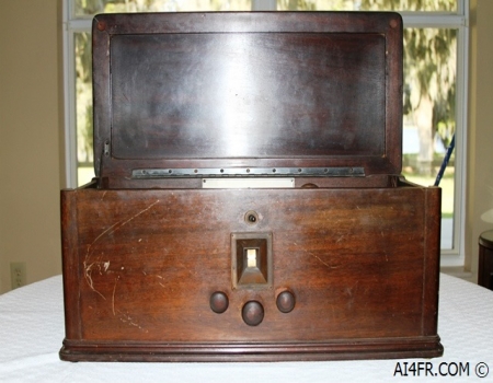
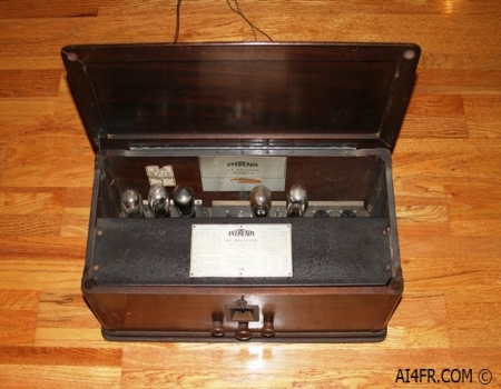
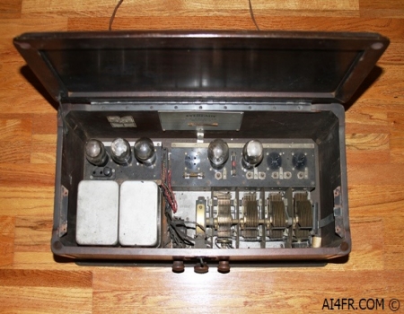
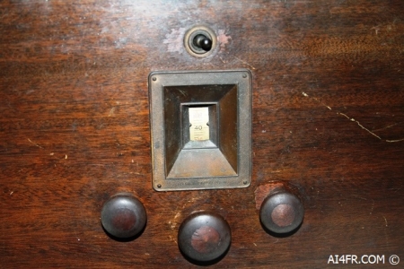
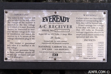
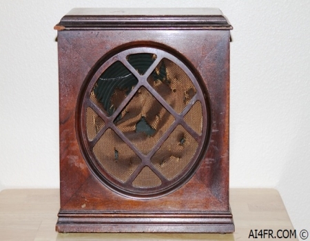
Production year 1928

The Eveready A-C Model 3 receiver was built by the National Carbon Company Inc. and, according to the metal I.D. plate found inside the receiver, this company was located in New York and in San Francisco. The plate goes on to state that the company is a "Unit of Union carbide and Carbon corporation".

The Eveready A-C Model 3 receiver employs 3 stages of neutralized Tuned Radio Frequency(TRF) amplification, along with a detector and two transformer coupled Audio Frequency(AF) stages, while ending in a push-pull power stage.

The Eveready A-C Model 3 is housed in a wooden cabinet and is only capable of receiving the AM broadcast band. The receiver has four controls on the front panel. Directly above the display or tuning dial is an on/off toggle switch. The knob on the far left is the adjustable variometer or antenna trimmer. The center knob directly under the tuning dial operates the four ganged variable capacitor and tunes the receiver to the desired frequency. The knob at the far right operates a potentiometer to control the volume. The three knobs are operated by turning them in a clockwise-counterclockwise fashion.

This receiver employs four type 26 tubes, a type 27 tube, two type 71a tubes and a type 80 tube for a total of eight tubes. Three of the type 26 tubes are used for the three RF stages of the circuit. The fourth type 26 tube is the first AF stage. The two type 27 tubes are for the push-pull audio output. The type 71a tube is the detector. The type 80 tube is the rectifier.

The power requirement of the Eveready A-C Model 3 is 105 to 125 volts A/C and it has a current draw of .5 amp at 25 cycles(Hz). Normal U.S. house current today operates at 120 volts A/C at 60 cycles(Hz). The receiver requires the use of an external speaker or headphones.  

The Eveready A-C Model 3 does not couple the antenna to the input of the first tube by way of the stationary coupler as encountered in similar circuit designs, but rather incorporates an adjustable variometer which is tuned by one of the ganged sections of the variable tuning capacitor. This antenna trimmer acts as an auxiliary tuning control which can be used to bring the antenna circuitry into resonance with the desired frequency. This is extremely helpful when attempting to bring in a weak signal as there is a marked increase in audio gain when the antenna input circuitry is in resonance.

Volume control is accomplished with the aid of a high resistance potentiometer which is located in the first Radio Frequency(RF) circuit. The volume control is electrically connected between the stator of the first RF section of the ganged variable capacitor and ground. The movable arm of the potentiometer connects to the grid of the RF tube.

The two transformer coupled AF stages are used with a push-pull power stage thus producing much better tone quality than can be obtained from an equivalent single large power stage tube. There are two main reasons for this. First, the demand for plate current in the two tubes is constant. When the plate current is decreasing in one tube it is increasing to the same extent in the other. This helps to avoid a fluctuating B supply voltage which occurs when the output power stage employs a single large tube. A fluctuating B supply voltage will also affect the other tubes of the set and produce a tendency to over-emphasize the notes of certain audio frequencies. Second, the two push-pull tubes are working out of phase with each other thus canceling out the second harmonic which is chiefly responsible for distortion when a single large power stage tube is being driven to a loud audio level.

The final audio output stage is coupled to the loudspeaker terminals through an output transformer. Besides aiding in tone quality, the output transformer prevents the heavy plate currents of the push-pull power tubes from reaching and destroying the windings on the loudspeaker. Thus the only voltage leaving the receiver is the safe low voltage of the secondary of the output transformer.

The circuit design of the Model 3 incorporates eight bypass capacitors. These bypass capacitors help to stabilize the receiver and contribute greatly to the tone quality of the set. The power unit contains the A, B, and C voltage supplies as well as the last audio stage and output transformer. The power transformer has three taps in the primary to compensate for the variations in line voltages encountered at different localities. These three taps correspond to line voltages of 105, 115, or 125 volts A/C and takes the form of three holes on a terminal board. A plug that comes with the set is inserted in the hole that corresponds to the line voltage in which the receiver will be operated.  

The photograph on the left is looking down with the hinged top cover in the open position. In this photograph the protective metal cover is in place. The metal cover has been removed in the picture on the right. At the bottom right of this picture the four section variable capacitor can be seen. In both of these pictures the receiver is seen with just five out of the eight tube compliment installed. The design of the cabinet being long and narrow is typical for a TRF receiver.

The TRF(Tuned Radio Frequency) receiver design was patented in 1916 by Ernst Alexanderson. This design is usually found composed of several tuned RF(Radio Frequency) amplifier stages followed by additional circuits in which to detect and then amplify the audio signal. The RF amplifier stage amplifies the incoming signal of the desired station while rejecting the other signals received by the antenna. Next the detector circuitry extracts the audio signal from the received radio carrier signal. Next one or more audio amplifier stages increases the power of the audio signal thus making it possible to drive a loudspeaker. Some TRF designs may not have an audio amplifier stage as these receivers were designed to operate with headphones instead of a speaker. The TRF circuit design was quite common in the 1920s.

The TRF receiver design is different than the superheterodyne design in use today and is more difficult to keep properly tuned and operating. Each of the tuned circuits in a TRF receiver will need to track to keep the narrow bandwidth tuning. Or said another way, each stage of the receiver must be individually tuned to the frequency of the desired station. Keeping these numerous circuits aligned is difficult. The thought behind this design was that each stage of the receiver would amplify just the desired signal while reducing the signal strength of near-by or interfering stations. This receiver design was eventually phased out and later replaced by the superheterodyne receiver that was invented by Edwin Armstrong in 1918 and is still in use today. The superheterodyne receiver simply requires the operator to tune the receivers' front end by using a single control knob set to the desired frequency while the following stages of the receiver operate at a fixed frequency that never changes. Although the TRF design was phased out decades ago in favor of the superheterodyne design, the TRF was resurrected in 1972 with the introduction of the ZN414 by Ferranti which placed the TRF radio receiver design on an integrated circuit. By using the TRF circuit design it allowed nearly an entire radio to be fitted into one small three pin package.

The picture on the left is a close up of the front panel controls on the Eveready A-C Model 3 receiver. As can be seen the receiver has four controls on the front panel. Directly above the display or tuning dial is an on/off toggle switch. The knob on the far left is the adjustable variometer or antenna trimmer. The center knob directly under the tuning dial operates the four ganged variable capacitor and tunes the receiver to the desired frequency. The knob at the far right operates a potentiometer to control the volume. The three knobs are operated by turning them in a clockwise-counterclockwise fashion.

The photograph on the right is of a metal ID plate that is attached to a metal cover that resides above the four ganged variable capacitor. The text on the left side reads as follows: IMPORTANT! The tubes in this receiver will give satisfactory life only when the voltage of the receiver is matched to the line voltage with which it is used. Eveready dealers are instructed to measure the line voltage at the time of installation and match the receiver to it by means of the voltage adjustment plug in the set. This receiver is guaranteed only when it is matched to the line voltage. To insure guarantee being in force, purchaser should fill in and sign enclosed card and mail it promptly.

The text on the right side of the metal plate is as follows: WARNING! Unless tubes are inserted in sockets of corresponding numbers, they will be burned out. If user's average line voltage is less than 105 volts or more than 125 volts, an Eveready voltage regulator should be employed to insure satisfactory operation and tube life.


I have always found it interesting to discover hidden treasures lurking inside of items. Whether under the buttplate of a rifle such as the previous owners I.D. tag found on a Swiss K31 or a hidden treasure found inside an old electronic device such as the Eveready A-C Model 3 receiver that is featured on this page. The photograph on the left is of just such a treasure. This piece of paper was folded neatly and tucked under the protective metal plate inside the receiver. The paper is an itinerary from St. Simon's church in Buffalo, New York and is dated April 16, 1939(first Sunday after Easter). On the front are the names Rev. William Baxter(rector), Rev. George O' Pray(curate), and Paul Miller(director of music). From there it goes on to the agenda of the day which was Holy Communion at 8:30am, Church school and adult bible class at 9:45am, Morning prayer and sermon at 1:00am(yes, it states 1am) and a Young people's fellowship at 7:30pm.

On the back of the piece of paper seen in the picture on the left is the weekly calendar. This calendar lists the itinerary of what St. Simons church has planned for each day of the week. In addition there will be a Mens club dinner and meeting on April 17th. The speaker at this meeting is Thurman Stoner and he will talk on the subject of "What can we do to save democracy". On the 18th of April there was planned an Acolyte guild meeting. Towards the bottom of the document there is a paragraph title "Forward movement of books" which states that new subscriptions are .25 cents which includes the cost of postage. The reader is instructed to call TR 1901 "if you wish your subscription continued". The last paragraph informs the reader about the fifth annual Bishop's Ball which will be held in the Ballroom of the hotel Statler on April 21st. There will be dancing from 9 to 2 with tickets costing $1.50 pre-sale and $1.75 at the door.

The photograph on the right is of the Eveready model 3 loud speaker as identified by a metal plate found on the bottom of the speaker cabinet. This I.D. plate goes on to state that the item was made by the National Carbon Company Inc. which was located in New York and in San Francisco. The plate goes on to state that the company is a "Unit of Union carbide and Carbon corporation".


Resource:

Old time radios by Joseph Carr

Antique Radios by David and Betty Johnson

1934 official short wave radio manual reprinted by Lindsay publications Inc.

Radio-Trician service manual by the National Radio Institute

Receiver trouble shooting and repair by Alfred Ghirardi and J. Richard Johnson

      AI4FR                                                                                                                                                                                                  AI4FR                                                                                                       AI4FR

Trump WON!! Biden CHEATED!!

Avoid the experimental gene therapy C19 DEATH shot!!  

Think Critically!!

Ukraine = Corruption

Was Hitler right?

Copyright © John Whitt 2022 All rights reserved. 

Created with the QTH.com SiteBuilder.