AI4FR Virtual Shack Tour 

Other Radios & Items


Production 1950's starting at a touch over $100 

How did this Geiger counter get into the radio section of this website? Well it is a receiver of sorts and I had no idea where else to place it.

The Professional model PRI 107B Geiger counter was built in the 1950's during the Uranium "gold" rush era. After the world had learned to split the atom the U.S. government through the Atomic Energy Commission was in high demand for Uranium ore. Geiger counters such as this one was sold to mineral prospectors in the hopes that they would make a fortune for finding deposits of Uranium ore. By 1958 though, the U.S. Government stopped purchasing Uranium ore and the "rush" effectively died. Keep in mind though that this was the 1950's and the cold war was beginning to heat up so the market for Uranium ore still existed but was not strong enough to keep many of the manufactures of Geiger counters in business. 

The Professional PRI 107B Geiger counter has 6 tubes which are as follows, 1U5, NE7, NE2, 1AF4, 1AF4 and a Geiger–Müller tube. The Geiger counter is powered by two 45 volt B batteries, one 22 1/2 volt C battery and two 1 1/2 volt D batteries. 

Basically the unit contains just 3 main tubes. The 1U5 tube together with its associated electrical circuitry is used to obtain the 900 volts which is necessary to operate the Geiger tube from the battery supply. A NE7 neon bulb operates as a relaxation oscillator to provide the basic frequency of about 100 cycles. This frequency is then amplified by the 1U5 tube and a high voltage is developed across the choke coil in its plate circuit. This is coupled to the diode section of the tube which rectifies the high voltage. A NE2 neon bulb is used in conjunction with a bleeder resister string consisting of 22 megohm resistors in an automatic voltage regulation circuit. Two 1AF4 tubes are used in a multivibrator type amplifier circuit which drives the indicating device and provides a means of sensitivity for the unit giving it a total of three ranges, X1, X10 and X100. The X1 range is the most sensitive, while the X100 range can be thought of as having the most attenuation.

Operation of the device is actually quite simple, hook up a couple of batteries, the tubes warm up, the light blinks, the meters moves and you are now receiving either gamma or beta radiation, or even both depending on the probe setting. 

Many thanks go to Doug Moore(KB9TMY). With out his help and guidance I would never have had this Geiger counter in the collection. Doug is a true expert on the workings and restoration of these devices and others like it. Thanks Doug for taking me under your wing and always being there!!

The picture on the right is a side view showing the Geiger–Müller tube probe in its holding place on the Geiger counter. The tube probe does not have to be removed to operate this item.  

The photograph on the left is a close up of the meter which reads in Milliroentgen which is the common unit of radiation intensity. This term is usually expressed in a unit of time such as Milliroentgen per hour and abbreviated MR/HR. 

Radioactivity is the process wherby certain elements emit particles or rays due to the disintegration of the nuclei of their atoms. The main types of radioactivity are alpha particles, beta particles and gamma rays.

Gamma rays penetrate matter in much the same manner as X-rays. Since gamma rays are the only type of radiation with appreciable penetrating power, they are the only ones that are important to the prospector. Beta particles have slight penetrating power and a reading from betas reflects only the radiation on the surface of the sample being tested. Since the radiation is not usually uniformly distributed through the sample a reading of beta radiation can give a false impression of the value of the ore. Alpha particles can be stopped by a thin sheet of paper and are therefore of no interest to the prospector.

The photograph on the right is a  close up of the markings on the Geiger counter. These first four photographs above were taken before the restoration process had begun.

These next two pictures show the components that are located under the chassis with the bottom cover removed. In the photograph on the left we can see the bumble bee capacitors and other components before they were replaced. In the picture on the right we can see some of the new parts installed. Some of the large orange drop capacitors have voltage ratings as high as 1600 volts. In this picture we can also see the NE7 neon bulb used in the relaxation circuit.

In a relaxation circuit the neon bulb has a very high resistance and no current flows through the circuit. Once the capacitor has charged up to a high enough voltage the bulb glows and current flows. The capacitor is very quickly discharge during this process and the neon bulb goes out. The capacitor then starts charging again and the process is repeated.


In these next two photographs we can see the two different battery positions. You may recall from the text above that the PRI 107 Geiger counter is powered by two 45 volt B batteries, one 22 1/2 volt C battery and two 1 1/2 volt D batteries. The picture on the right shows the D cell battery holders.

In order to use this item today in a reasonable manner it was necessary to install an inverter in the power supply circuit so modern batteries could be used. The two B batteries which are 45 volts each are difficult and expensive to acquire today. While it would be possible for the operator of the Geiger counter to string together two different groups of five 9 volts batteries in series to produce two 45 volt power sources. But, that would be 10 batteries to drag along and deal with while out in the field and the operator would only be a third of the way done with the power requirement's. Still needed are the additional batteries to make a 22 1/2 volt power source, and the two D batteries. Instead of messing with all of them batteries, another option would be to simply purchase the correct batteries, but these uncommon battery sizes are rather expensive. So the best choice I felt was the inverter route. With the inverter that I installed, the device runs perfectly on two D batteries and four double A batteries. Plus, all of the batteries and the inverter neatly and easily fit inside the unit.   

The photograph on the left shows three of the vacuum tubes that are used in the Professional PRI 107B Geiger counter. Notice the D cell holder on the left.

The photograph on the right is of a radioactive sample which is provided with the Geiger counter. It is stamped with its value in Milliroentgens and it will give a reading equal to this value when held flat against the face of the Geiger tube with the shield in the open position. The sample should be moved about to the position where it gives the maximum reading. There is a slot built just for this item on the front of the Geiger counter case. For some reason, this item is missing from many of the units that are found for sale today.

Why is such an example supplied with the Geiger counter? These Geiger counters are made to operate out in the field and after an extended period of operation the batteries will start to run down. When this happens the operator can take this radioactive example and adjust the Geiger counter so it will show the proper reading through out the life of the batteries. This adjustment is located right next to the handle on the top of the unit and no disassembly is required to make adjustments except for the removal of a dust cap. 


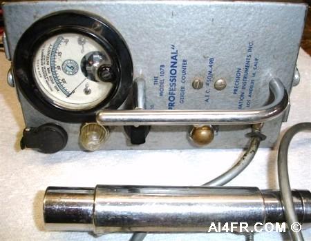
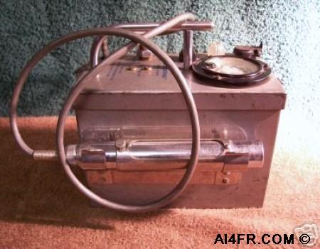
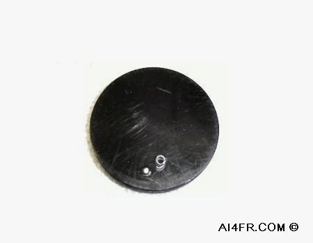
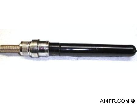
The photograph on the left shows the probe which contains the Geiger–Müller tube. The opening is to allow the detection of beta radiation. With it closed, the Geiger counter will only detect gamma particles. In the open position, both gamma and beta radiation detection is possible. It is shown here in the open position.

The photograph on the right is a picture of the Geiger–Müller tube which is located inside the metal body of the probe in the picture on the left. This is now an expensive tube that is becoming extremely difficult to find today.


What is a Geiger–Müller tube?

The Geiger–Müller tube or "GM tube" is what I consider to be the heart of this Geiger counter. The GM tube derived its name from both Hans Geiger and Walther Müller. Hans Geiger invented the device in 1908, and then 20 years later, Walther Müller, while working with Hans Geiger, developed it even further. The GM tube is the receiving, or more accurately, the sensing element of a Geiger counter. The GM tube can detect a single particle of ionizing radiation, and will typically produce an audible click in the speaker of the Geiger counter for each particle detected. The GM tube consists of a tube that is filled with a low pressure (~0.1 atmospheric pressure) inert gas. This is usually neon gas, but helium and argon gas are used as well.

Between the electrodes inside of the GM tube is a potential difference of several hundred volts but there is no current flowing. The inside walls of the tube are either entirely metal or will have their surface coated with a conductor to form the cathode, while the anode is a wire passing up through the center of the tube. When ionizing radiation passes through the tube, some of the gas molecules will be ionized, thus creating both positive charged ions, and electrons. The strong electric field that is created by the GM tube's electrodes then accelerate the ions towards the cathode and the electrons towards the anode. The ion pairs will have gained sufficient energy to ionize further gas molecules through collisions on the way, creating an avalanche of charged particles. This results in a short, intense pulse of current which passes (or cascades) from the negative electrode to the positive electrode which is measured and then registered in the speaker of the Geiger counter.

Digging in a little deeper into the operation of the tube, it is, in short, a type of gaseous ionization detector that has an operating voltage in the Geiger plateau. Depending on the characteristics of the specific counter, the exact voltage range may vary. In the Geiger plateau region the potential difference in the counter is strong enough to ionize all the gas inside of the GM tube when triggered by the incoming ionizing radiation whether it is alpha, beta or gamma radiation.

Voltages below the Geiger plateau region will not be high enough to cause a complete discharge which results in what is known as a limited Townsend avalanche. In this state, the GM tube acts as a proportional counter where the output pulse size depends on the initial ionization that was created by the radiation. On the other end of the spectrum, a higher voltage will cause a phenomenon known as "quenching" in which the positively charged ions will be drawn to the cathode creating a continuous pulse in the counter.


Resource:

Plectron instruction manual

Doug Moore's book detailing the restoration of the PRI-107B

      AI4FR                                                                                                                                                                                                  AI4FR                                                                                                       AI4FR

Trump WON!! Biden CHEATED!!

Avoid the experimental gene therapy C19 DEATH shot!!  

Think Critically!!

Ukraine = Corruption

Was Hitler right?

Copyright © John Whitt 2022 All rights reserved. 

Created with the QTH.com SiteBuilder.