AI4FR Virtual Shack Tour 

Hallicrafters Items


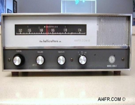
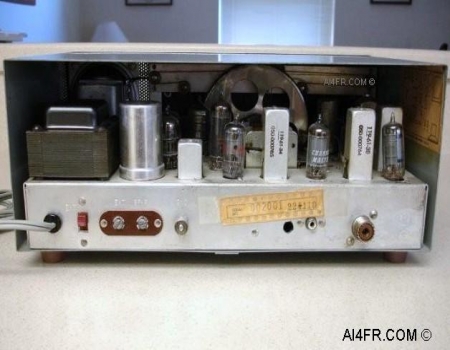
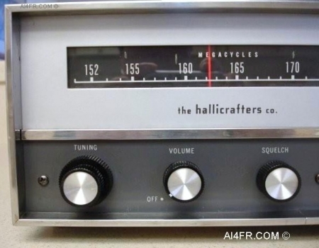
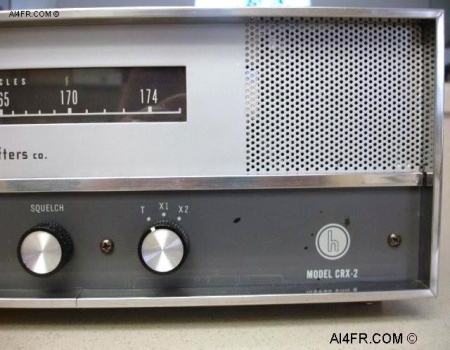
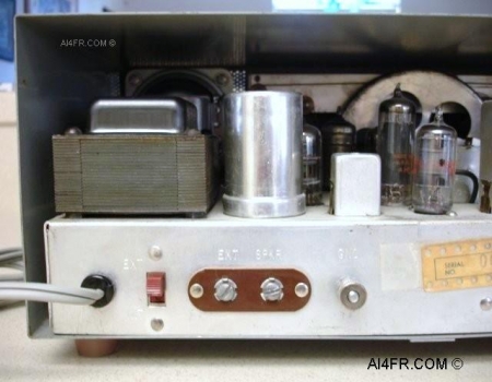
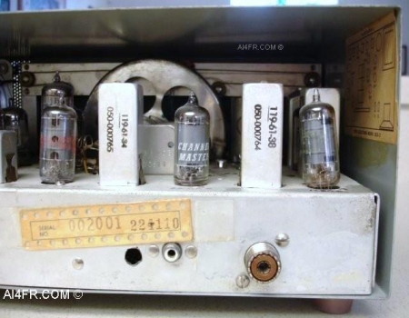
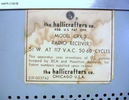
Production Year 1962 - 1963 at $109.95 

The Hallicrafters CRX-2 is a 10 tube, single band, dual conversion, FM receiver. It has a frequency range of 151 MHz to174 MHz. The radio has two different intermediate frequencies(I.F.) which are 455 KHz and 10.7 MHz. The front panel controls are as follows from left to right, the Main Tuning knob, On/OFF and Volume control, Electronic Squelch control, and three position Crystal/Main tuning selector knob. The radio also features a Vernier tuning control on the same shaft as the main tuning knob. The separate Vernier control for the main tuning knob allows the operator to quickly move to a different frequency using the main tuning knob and once a station is found, the operator can then fine tune the station with the Vernier control for the best reception.  

The radio also has a space for two optional plug in CR-23/U type crystals for quick tuning of a popular frequency. The CRX-2 features a built in speaker behind the front panel. This loudspeaker which faces out towards the front of the unit is of the permanent magnet moving coil design. Received signals exit through a perforated section on the front of the unit. The power consumption of the radio is 51 watts with a power source of 117 volts AC at 50 to 60 cycles. The input power source should be in the range of 105 to 125 volts AC at 50 to 60 cycles. If an external speaker is used, Hallicrafters suggest that it be in the range of 3 to 4 ohms.

The tubes are as follows, a 6ER5 = RF Amplifier, 6BL8 = 1st Mixer & Oscillator, 6BL8 = 2nd Mixer & I.F., 6BL8 3rd Mixer & Crystal Oscillator, 12BA6 = I.F., 12AT7 = Crystal Oscillator, 12BA6 = I.F., 6DT6 = Detector, 6BL8 = Squelch & 1st Audio amplifier and a 12AQ5 as the Audio Output. The rectifier consists of two silicon 1N3194 diodes. The dimensions of the radio are 13 1/2 inches wide by 5 3/4 inches high by 8 inches deep. The CRX-2 weighs in at 15 1/2 pounds.  

The photograph on the right is of the back of the receiver. This picture displays the tube compliment and some of the other major components that are found on the top of the chassis. Starting at the left, the back panel plugs and switches are as follows, AC power cord, a red colored internal/external speaker switch, external screw terminal speaker connections, ground connection, an RCA style antenna connection which is located underneath the paper sticker and an SO-239 connection on the right. Hallicrafters recommends that a coaxial transmission line of between 50 to 75 ohms should be used for the SO-239 connector.

A very similar receiver is the Hallicrafters CRX-1 which also receives only in FM mode and covers the frequency range of 30 MHz to 50 MHz.


The photograph on the left is a close up of the left front of the receiver. The control knobs shown in this picture are the Main/Vernier tuning on the left, On/Off and Volume control in the middle and on the right is the Electronic Squelch control. A good representation of the slide-rule pointer and main frequency display can also be seen in this picture.

The photograph on the right is a close up of the right front of the radio. The control knob of interest in this picture is the three position Crystal/Main tuning selector knob. The optional crystals for this receiver are of the CR-23/U type. One crystal is required for each dial setting(X1 and X2) for a total of two crystals. To find the correct crystal frequency to purchase, a little bit of math is in order. Say you wanted a crystal frequency that would allow you to quickly monitor 155.25 megacycles on either of the two dial settings, X1 or X2. The formula for this is the crystal frequency in megacycles equals the transmitter frequency minus 10.7 then divided by 4. Using our example frequency of 155.25, we would minus that by 10.7 which equals 144.55, then divided by 4 which gives us 36.1375. Then we need to carry out the calculation to four decimal places, 36.1375, 37.0500 and finally to 40.215 cycles.

Back in the early 1960's when this receiver was manufactured, the Hallicrafters company briefly explains about the different radio services found in the frequency range of this receiver. I quote their statement here, "These services include the receiving of emergency vehicle communications, bus communications, private telephone use, forestry signals, power company communications, and other industrial communication uses.".  

The photograph on the left is of the left side back of the receiver. As can be seen, this radio has its own internal AC power supply circuitry as evident of the AC power cord, large black transformer and the can type electrolytic capacitor. I mention this power supply circuitry due to having another CRX-2 receiver in the collection that does not have this built in AC power supply. The red switch located next to the power cord is used to select from either the front internal speaker or the speaker screw terminals located next to it. Besides connecting an external speaker to these screw terminals, Hallicrafters states that they can be used for headphones or a recording device. The manual goes on to say that any size of external speaker may be used and that a permanent magnet type speaker with 3 to 4 ohms is preferred. Across the external speaker screw terminals should be a 12 ohm 1 watt resistor when the internal speaker, headphones or a recording device is being used. This resistor should be removed when using an external speaker.

The photograph on the right is of the right side back of the receiver. In this picture we can see both of the antenna inputs. The RCA type connector is found underneath the serial number paper sticker and the SO-239 coaxial connector is on the right. The cut-out hole to the left of the RCA connector was probably added by a former owner. The tube on the far right is not set properly in the socket which gives it a leaning tower of Pisa appearance.  

The photograph on the left is of the bottom of the CRX-2 receiver. Unlike the feet on the CRX-1 which are gray in color, the factory feet on this CRX-2 is a reddish brown color.

The picture on the right is a close up of the sticker that is found on the bottom of the receiver. This sticker reads as follows, "the hallicrafters co. REG. U.S. PAT. OFF. MODEL CRX-2 RADIO RECEIVER 51W. AT 117 V. A.C. 50-60 CY. This apparatus uses inventions of U.S. patents licensed by RCA and Hazeltine Research Inc. Patent numbers supplied upon request. the hallicrafters co. 031-003742 CHICAGO U.S.A.".  


Resources:

Radios by Hallicrafters with Price Guide by Chuck Dachis

Hallicrafters owners manual

Sam's photofacts by Howard W. Sams & Co., Inc.

      AI4FR                                                                                                                                                                                                  AI4FR                                                                                                       AI4FR

Trump WON!! Biden CHEATED!!

Avoid the experimental gene therapy C19 DEATH shot!!  

Think Critically!!

Ukraine = Corruption

Was Hitler right?

Copyright © John Whitt 2022 All rights reserved. 

Created with the QTH.com SiteBuilder.