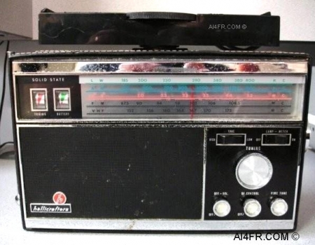
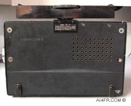
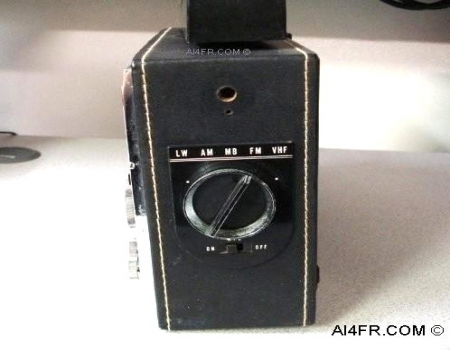
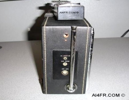
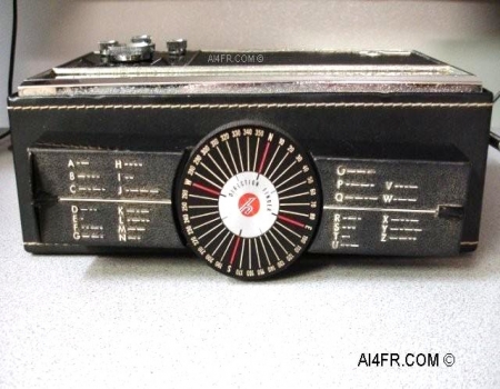
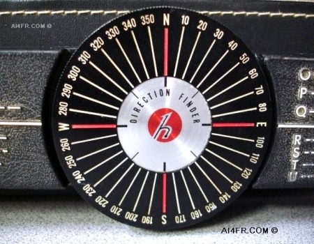
Production Year 1969-70 at $129.95 The Hallicrafters CR-44 is a 5 band, Superheterodyne, AM and FM portable radio with 16 transistors and 4 diodes in its circuitry. The coverage of the 5 bands begin at 185 kHz through 400 kHz, from there it jumps to the standard AM broadcast band, then it picks up again at 2.0 MHz through 5.2 MHz on the SW bands, from there it moves to the standard FM broadcast band, and lastly the receiver covers in FM only the frequency range of 152 MHz through 173MHz. This receiver employs two different intermediate frequencies of 455 KHz and 10.7 MHz. The 455 kHz I.F. is used for the lower three bands, while the 10.7 MHz I.F. is used for the FM broadcast band and the VHF band. The radio can be powered by a wall transformer or 6 VDC using 4 "D" cell batteries ran in series. The AC adapter for the CR-44 is the Hallicrafters HA-36 that was produced in 1969 and 1970. The front panel controls include an On/Off switch, a frequency fine tune adjustment, a Direction Finding On/Off switch, a Tone control, a Lamp/Meter selector switch and a Main tuning dial. Besides the controls and frequency display, located on the upper left side of the front panel are two separate meters. The meter on the left is used for direction finding, while the meter on the right displays the condition of the batteries. The operator has the option of turning each of these meters off to help conserve battery power. The loudspeaker which faces out towards the front of the unit is of the permanent magnet moving coil design. Received signals exit through a perforated section on the front of the unit. The radio is capable of an audio output of 500 milliwatts with 10% distortion at 300 milliwatts. With no input signal present, the battery drain is 18 milliwatts. The sensitivity of the receiver is as follows, on band 1(LW) it is 400 uV/M for a 12 DB signal to noise ratio, on band 2(AM) it is 250 uV for a 12 DB signal to noise ration, on band 3(MB) it is 175 uV/M for a 12 DB signal to noise ratio, on band 4(FM) it is 10 uV for a 20 DB signal to noise ratio and for band 5(VHF) it is 12 uV for a 20 DB signal to noise ratio. The selectivity of the 455 KHz IF is 5KHz to 10 KHZ at 6DB. The 10.7 MHz IF sports a selectivity of 130 KHz to 200 KHz at 6 DB. The IF rejection of this receiver is different on most of its five bands. On band 1(LW) it has a minimum IF rejection of 10 DB. On band 2(AM) it has a minimum of 24 DB IF rejection. On band 3(MB) the receiver has a minimum IF rejection of 30 DB. On both bands 4(FM) and 5(VHF) it has a 40 DB minimum IF rejection. A really neat feature of this receiver is the rotating ferrite rod antenna that is located on the top of the radio. This nifty feature incorporates a compass so the radio can be used for direction finding of RF. This receiver also features a telescoping whip antenna that is located on the left side. As with many items from this era, the CR-44 was manufactured in Japan. The photograph on the left shows the front of the radio while the photograph on the right is of the rear. Hallicrafters also manufactured a CR-44A which had an extra transistor bringing the total to 17. |