AI4FR Virtual Shack Tour 

Electronic Repair Tips


There has probably been thousands of magazine articles and many numerous pages appearing in electronic publications about the proper way to solder PL-259 connectors to coaxial cables. I have discovered a way to help improve this process, or stated more accurately, my success of it. Browsing through the pictures on this web page really tells the tale, but I will attempt to put a description with each picture for further clarification.

The photograph on the left is the starting point. Here we have a PL-259 connector that has not been modified since it left the factory. Notice the round holes that we are supposed to apply the solder to so that the PL-259 makes a good connection to the shield of the coax. The modification described on this page involves the enlarging of these holes. Also in this picture is the attachment for the Dremel tool that I use for the modification.

The red arrow in the picture on the right is pointing to the section of the PL-259 that has been modified. The outside surface of the round solder hole on the PL-259 has been expanded and made into an oval shape. This process takes just a few seconds with the Dremel tool. I normally end up doing this grinding modification to each of the four holes on the PL-259. The PL-259 connector can often be found with some type of external plating such as chrome or with some other alloy. The manufacturers seem to find a plating that solder has a tough time adhering to. The PL-259 modification on this page has the added benefit of removing that plating and giving the solder a surface that it likes a whole lot better.


These next two photographs show the modified PL-259 connector with the RG-8/U coax installed and ready to be soldered. After the grinding and before the coax is installed on the PL-259 , I make it a point to clean out any of the debris from the grinding process that may have worked its way inside of the PL-259. The red arrow in each of the pictures is pointing to the modification. The larger oval shape of the hole allows for much greater access for the tip of the soldering iron and for the solder to reach the shield of the coax. The tip of the soldering gun can touch and apply heat to both the coax shield and the PL-259 for a proper solder connection. I have found that by doing this modification, a cold solder joint and damaged dielectric are more easily avoided.  

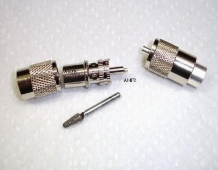
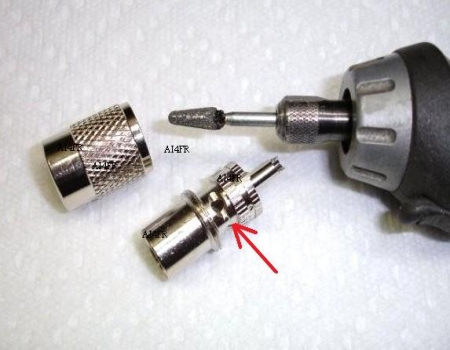
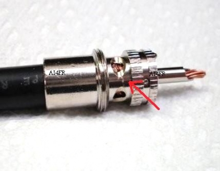
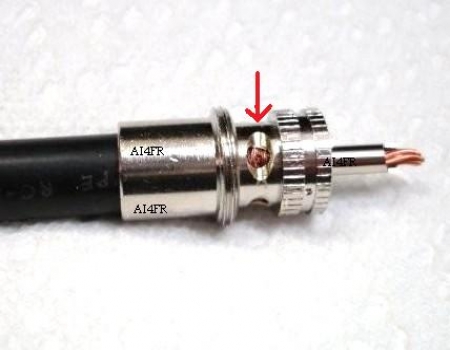
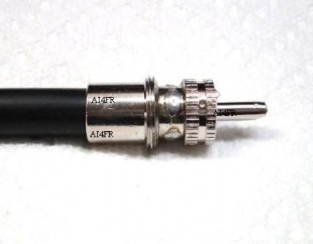
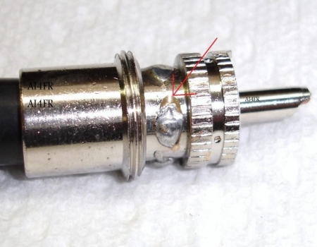
The red arrow in the photograph on the left is pointing to the modified section on the PL-259. When I made this solder connection, I intentionally applied a little less solder just for this picture in the hopes that it would further explain the process.

The picture on the right is of the finished product. While it is probably not necessary to solder all four of the holes on the PL-259 connector, I find myself doing it this way just about 100% of the time. Using the oval hole modified PL-259, and possibly with the assistance of applying solder to all four of the holes, I have never had a PL-259 connector fail due to faulty construction. Now I have had to clean the contact surfaces of a few as oxidation slowly builds over the years. To perform that task, I use a Q-tip soaked with DeoxIT.


Taking the above idea and making it a whole lot better.

I received a tip from my friend Paul, K0UYA, that does just that. Paul's idea is to use a fine pitch hacksaw blade or the proper Dremel tool attachment in order to remove all of the metal between two adjacent holes on the PL-259. The slots should be roughly the same size or slightly smaller then the original holes. When done correctly there will be two slots, possibly in the shape of a dog bone each, between two opposing pairs of holes thus producing two slots and two solid areas on the PL-259. The new slots will expose much more of the braid for a "government lab approved" connection and will knock down on the thermal mass of the PL-259 connector for faster soldering, which means that there is much less of a chance to damage the coax.

Paul has informed me that he has been performing this trick for the last 40 plus years with great success. It was shown to him by Mr. Wayne Stensland of Kelly, IA and a former scientist at the Ames Laboratory at ISU. Where did Paul's elmer learn of the idea? Paul suspects that it possibly dates back to a method used by someone in the instrument shop at ISU.  

      AI4FR                                                                                                                                                                                                  AI4FR                                                                                                       AI4FR

Trump WON!! Biden CHEATED!!

Avoid the experimental gene therapy C19 DEATH shot!!  

Think Critically!!

Ukraine = Corruption

Was Hitler right?

Copyright © John Whitt 2022 All rights reserved. 

Created with the QTH.com SiteBuilder.