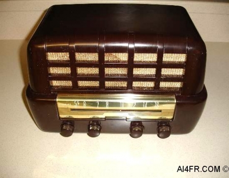
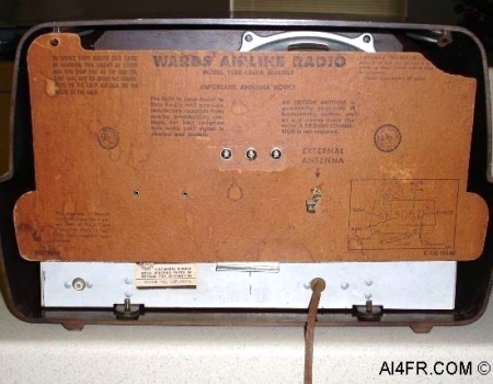
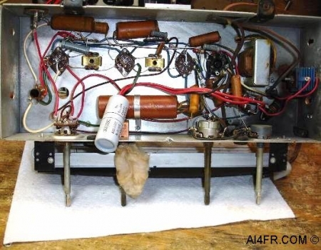
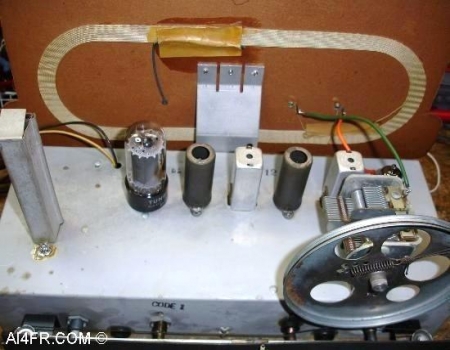
Production Year 1951 Manufactured by Montgomery Ward & Co., this model Airline 15BR-1547A is a 4 tube Super-Heterodyne receiver which uses an IF frequency of 455 kHz. The receiver frequency range is 540kc to 1600kc which makes it an AM broadcast band only receiver. The tubes and their functions are as follows, a 50L6 as an Output Amplifier, a 12AT6 or 12AV6(can use either) as a Detector, AVC and Audio Amplifier, a 12BA6 as the IF Amplifier and a 12BE6 as the Converter. The power source is 115 volts and the receiver uses a PM speaker which has an impedance of 3.2 ohms. The power out is 1 watt undistorted and 2 watts maximum. The selectivity at 1000kc is 50kc and the sensitivity is 20 microvolts for .05 watts output. It is a rather large bakelite radio with four knobs. Starting at the left the control knobs are as follows, a Tone control, On/OFF and Volume control, a Tuning knob, and a Phono/AM control. The phono/AM selector will allow the operator to plug in a RCA jack from a phonograph, and play it through the radio. The connector for this jack is located on the left rear of the back panel. This receiver has a built in loop antenna but it also has a connection on the rear for an external antenna. The super-heterodyne circuit was invented by Edwin Armstrong in 1918. The circuit of a super-heterodyne(superhet) receiver employs the mixing of signals which provides superior selectivity, frequency stability, and sensitivity when compared with simpler designs such as regenerative, Tuned Radio Frequency(TRF) or Neutrodyne receiver circuits. The superhet, which is still in use today, mixes the received signal with that of an internally produced signal referred to as the intermediate frequency(IF) which allows the receiver to more conveniently process the received radio signal. The detector, intermediate amplifier, and a-f amplifier of a superhet receiver are actually equivalent to a complete TRF receiver by themselves. The main difference from complete Amplitude Modulation(AM) TRF receiver circuits are that the IF section of a superhet is fixed tuned that is, the resonance is set at one frequency and reception is possible only with signals of the intermediate frequency. The diode detector used in a superhet is somewhat less sensitive than the types used in TRF receivers such as grid leak, square law, linear plate, and similar types. The signal from the antenna is filtered to reject most of the undesired frequencies and eventually amplified. A local oscillator inside the receiver produces a sine wave(usually 455Kc) that mixes with the received and filtered signal and thus shifting it to a specific intermediate frequency(IF). This IF signal is then filtered and amplified and depending on the circuit it can be further processed in additional ways. Next the demodulator takes this IF signal and demodulates it to recreate a copy of the original information sent in the transmitted radio signal. There are several different superhet circuit designs such as single, double, and triple, conversion. The word Superheterodyne is a contraction of the words supersonic and heterodyne. In this case the word supersonic(super) indicates those frequencies that are above the range of human hearing. The word heterodyne is derived from the Greek roots where hetero indicates different, and dyne indicates power. Putting all this together superheterodyne simply means frequencies that are above human hearing with a different power. Both of the pictures above show the radio after it was restored. |