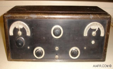
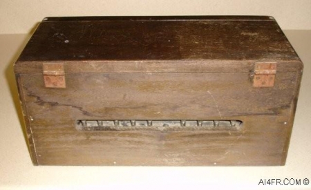
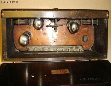
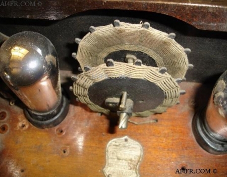
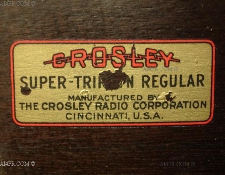
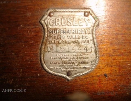
Production year 1924 The Crosley Super Trirdyn Regular first appeared in 1924. An issue of the Crosley Radio Weekly dated October 12, 1925 lists this radio for sale at a price of $45.00 without any accessories, which was a $5.00 drop in the regular price. The caption in this issue of the Crosley Radio Weekly reads as follows: "COAST TO COAST RADIO AT A VERY LOW PRICE Sell the Super Trirdyn Regular for $45.00" That was the message dispatched last week by Powel Crosley, Jr., to his authorized dealers. The effect was instantaneous. Congratulations and messages of thanks poured in. Dealers appreciated the added opportunity of a more rapid turn-over. Consumers appreciated the savings. The Super Trirdyn Regular is exactly the same as the the Super Trirdyn Special except it is installed in a slightly smaller cabinet. It is a coast to coast receiver, in which the three tubes do the work of five or six. Lowering of the price will result in an increased demand for this radio, and dealers must be prepared to meet the requirements of their customers. Place an order immediately with your distributor - order at least half a dozen Super Trirdyn Regular radios." The Crosley Super Trirdyn Regular is a broadcast band only receiver that INCORPORATES a total of three number 201 tubes. The receiver requires a set of headphones or a loud speaker such as the Crosley Musicone for operation. As was the case with a number of radios from this era, the power source was not AC, but rather DC and often using batteries. To power the Crosley Super Trirdyn Regular by batteries today will prove difficult and expensive due to the voltages the set requires. One way to get around this problem would be to string a number of batteries in series. For example, say you're in need of a battery with 90 volts. Simply take around ten 9 volt batteries(cell) and run them in series(positive post of one cell to negative post of next cell and so on). The output voltage would be 90 volts, but the Ah(amp hours) or capacity stays the same. In other words, the string of batteries will run down quickly. The battery string has the voltage to run the radio but the capacity to keep it running for an extended period of time is not available in the battery string. The opposite also holds true. If the batteries were wired in parallel(positive post of one cell to positive post of next cell), the voltage would remain at 9 volts but the capacity of the battery string would be the combined total of the capacity(amp hours) of all the batteries in the string. The Crosley company claims that it is a special combination of their circuit that allows this receiver to run from 3 tubes instead of five or six. The company explains the circuit as having a stage for tuned RF(radio frequency) amplification, another part of the circuit for Armstrong regeneration and a third used for reflexed amplification. Tuned radio frequency is described in the text below the next set of pictures. Armstrong regeneration is basically amplification via positive feedback while Reflex amplification simply means that one or more tubes are used for both RF amplification and audio amplification. One issue with regenerative amplifiers when it creates these very high gains is that they can easily become unstable and cause the circuit to oscillate. The radio operator must have the experience and knowledge to tweak the amount of feedback on a constant basis for good reception of the desired signal. Crosley explains it this way: "Being the user of a regenerative receiver you know that if the tickler is tuned to nearly parallel to the tuning inductance a click is heard in the headphones and stations will come in distorted and mushy. The set is oscillating and it is only when the set is oscillating that you can by any chance bother your neighbors, because it is only when a vacuum tube is oscillating that it will transmit current from the antenna. In as much as a regenerative receiver will not give the user good results while oscillating and causes much trouble to neighboring fans, the tickler should, at all times, be kept retarded enough to keep the set from oscillating." Crosly explains their circuit as follows: "In Armstrong regenerative sets a coil of wire or inductance is connected on one end to the antenna and the other end to ground. A third connection on the coil goes to the grid of the detector tube and a fourth connection to one side of the filament. Inside the first inductance mentioned or in inductive relation(parallel) to it is found a second coil known as the tickler or plate coil. this coil has one connection to the plate of the detector tube and the other to the phones or amplifying transformer as the case may be. The circuit is now completed by a connection from the other side of the phones to the plus side of the B battery and a connection from the minus side of the B battery to the filament of the tube. If the broadcasting station you wish to tune in is operating on 300 meters(1 MHz) the tuning inductance is tuned until the receiver wavelength is 300 meters, or in resonance with the station transmitting. This being done the high-frequency oscillations of the station pass into the receiver from the antenna, through the detector tube where they are rectified to audio frequencies and on to the headphones where these frequencies are change to sound waves. The tickler is in the circuit to make the detector regenerate. By regeneration we mean that the signal, after passing through the detector tube once, is fed back, due to the inductive relation of the tickler to the tuning inductance, into the tuning inductance and so forms the cycle, being fed from one coil to the other thousands of times." The size of the radio is 17-1/2" wide, by 71/2" high, by 7" deep. All of the photographs on this page show the radio in the condition it was received. I will post pictures of the restoration process and the completed radio once work begins on this receiver. |