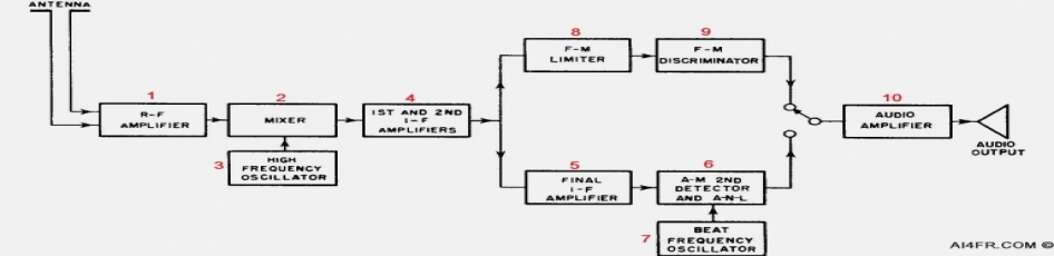
Receive theory of operation. The block diagram shown above displays the circuit of the Hallicrafters S-36. You may have recognized the first part of this circuit up to the 2nd IF amplifier stage as that of a conventional superheterodyne receiver. At this point the output of the 2nd IF amplifier is fed into two channels, namely, the FM signal channel and the AM signal channel. The FM channel consists of the FM limiter and discriminator while the AM channel consists of an additional IF amplifier stage and 2nd detector stage. The AM and FM mode is selected by a switch on the front panel. The demodulated signal from the selected channel now feeds the audio amplifier which in turn feeds the speaker. A more detailed description with corresponding numbers for each stage in the block diagram is below. Since the circuit function for all 3 bands is essentially identical, the description below will focus mainly on band 3 which has the highest frequency range and also covers more frequencies then any other band. 1. The RF amplifier stage employs an acorn 956 pentode tube in a conventional class A amplifier circuit. Received signals from the antenna are first fed to the primary winding of transformer T3. The transformer secondary winding is tuned by two front panel controls, the ganged tuning capacitor section C1A and the antenna trimmer capacitor C2. RF signals that are selected by the parallel resonant circuit are now applied to the grid of tube V1 and appear in greater amplitude across the primary of transformer T6. The parasitic resistor R26 prevents the unwanted oscillations in this stage and also tends to stabilize the amplifier. The self bias for this stage occurs due to capacitor C4 by-passing resistor R1. Resistor R2 and capacitor C5 act as a decoupling network for the screen of tube V1, while resistors R3 and R4 along with capacitors C6 and C78 act as decoupling networks for the plate circuit. The signal from the primary of transformer T6 is coupled to the grid of tube V2 inductively by transformer T6 and capacitively by capacitor C7. The small amount of coupling from capacitor C7 improves the response at the high frequency end of the band, thus equalizing the RF signal amplitude over the tunable frequency range. The signal that is developed at the grid of tube V2 now moves to the next stage of the circuit which is the mixer stage. 2. The Mixer stage employs an acorn 954 pentode tube in a cathode coupled mixer circuit. The secondary winding of transformer T6 is tuned by the ganged tuning capacitor section C1B and trimmer capacitor C65. RF signals selected by the parallel resonant circuit are now applied to the grid of the mixer tube V2. A signal from the local oscillator that is 5.25 MHz higher in frequency then the received signal on band 1, and 5.25 MHz lower in frequency then the received signal on bands 2 and 3 is fed to the mixer tube through the cathode and provides the difference in frequency of 5.25 MHz for the IF amplifier stage. 3. The oscillator circuit consists of an acorn 955 triode tube in a tuned plate, untuned grid type of oscillator circuit. The frequency of this oscillator is determined by a resonant circuit consisting of the secondary winding on transformer T9 and section C1C of the main tuning capacitor in parallel. On band 3, capacitor C11 is used to trim transformer T9, although it remains in the circuit on the first two bands. The RF energy is fed from the plate of tube V15 to the tuned circuit by the DC blocking capacitor C56. The decoupling network in the plate circuit of the oscillator tube consists of four components, resistors R62, R63, inductor L1, and capacitor C55.. Resistor R66(band 3) and capacitor C57(all bands) in series with the feed back winding of transformer T9 provide grid voltage across resistor R64 for the oscillator tube. The oscillator voltage is supplied for the mixer stage by a 3rd winding on transformer T9 which is fed to the mixer tube V2 through capacitor C9. 4. The 1st and 2nd IF amplifier stages employ pentode tubes 6AC7 and 6AB7. The IF amplifier coupling transformers T10, T11 and T12 for the 1st and 2nd IF stages are tuned to 5.25 MHz by adjusting the powdered iron core slugs in both the primary and secondary windings. The gain of the 1st and 2nd IF stages is adjusted by the RF gain control on the front panel that is connected in series with the cathodes of both of the pentode tubes,.to provide sensitivity control for the receiver instead of the more commonly seen practice of varying the gain of the RF amplifier stages. The reason it is done this way is to allow the RF amplifier stages to operate at maximum gain, thereby providing a high signal to noise ratio at all sensitivity settings. The AVC grid voltage is applied to this section of the receiver through the decoupling networks C12, R10, C16 and R19. The AVC voltage is supplied by the 2nd detector tube V6 during AM reception and a small amount of voltage is also supplied for a similar purpose, from the limiter tube V7 during FM reception. Since the 1st and 2nd IF amplifier channel is varied to provide a relatively sharp frequency response for AM reception and a relatively broad frequency response for FM reception. The selectivity of the IF amplifier is controlled by switching in a 3rd winding which varies the coupling between the primary and secondary windings. In the sharp position, the coupling winding is disconnected and only the coupling between the primary and secondary windings determine the bandwidth of the IF amplifier. In the Broad position, the coupling winding is introduced to increase the coefficient of coupling between the primary and secondary windings. This increase coupling broadens the IF amplifier frequency response to accept FM signals. The signal voltage supplied by the 2nd IF amplifier is fed to the limiter and discriminator for FM reception and to the 3rd IF amplifier stage and 2nd detector for AM reception. 5. The final IF amplifier stage used for AM reception employs a 6SK7 pentode tube that is connected in a conventional class A amplifier circuit. This stage is coupled by transformers T12 and T13 which are tuned by adjustable powdered iron core slugs. Resistor R25 is bypassed by capacitor C21 and provides the self-bias for this stage. The gain of this stage is not varied as it was seen above for the 1st and 2nd IF amplifier stages. The amplified signal voltage developed across the secondary of transformer T13 is now fed to the 2nd detector for demodulation of AM signals. 6. Both the 2nd detector and the ANL stages employ a single 6H6 duo-diode tube. One diode section of tube V6 serves as a detector for AM signals by rectifying the modulated carrier. The RF for this type of detection consists of resistor R31 and capacitors C24 and C26 that are connected in a pi-section. The AVC voltage and audio frequency voltage is obtained from the load and voltage divider resistors R33, R34 and R36. Resistor R35 and capacitor C8 serve as AVC decoupling. The remaining diode section of tube V6 serves as a ANL as follows: capacitor C25 becomes charges by the rectified carrier voltage and the time constant of this capacitor and the filter network associated with it is such that the audio frequency voltage variations do not alter this charge. During a severe noise pulse, however, the cathode of the diode plate connected to capacitor C25 becomes more negatively charged then the charge held by capacitor C25, hence, current flows shorting the audio voltage to ground through capacitor C25 until the cathode voltage of the ANL diode again reaches a less negative potential than its plate and capacitor C25 acquires its normal charge again. By shorting the audio voltage to ground during a noise pulse, the ANL circuit prevents the objectionable noise pulses from reaching the audio amplifier stages. 7. The BFO employs a 6J5 triode tube in a modified Hartley oscillator circuit. The oscillator frequency is adjusted by a movable powdered iron core within the field of coil L5. This iron core adjustment sets the oscillator frequency to 5.25 MHz. The fine adjustment of the oscillator frequency required to provide control of the beat note frequency is controlled by variable capacitor C60 located on the front panel and known as the Pitch control, which tunes a small portion of the total oscillator coil L5. The BFO switch controls the use of the oscillator by breaking the plate voltage lead to the tube. The decoupling network R60 and C52 prevent the oscillator signal from reaching the other stages through the B voltage supply. 8. The FM detector consists of a limiter stage and a discriminator stage. The 6AC7 limiter tube V7 is fed by the 2nd IF transformer secondary winding along with the 3rd IF amplifier tube V5 for FM reception. The limiter stage operates as a saturated amplifier in which the output voltage remains constant over a large range of input voltage levels, thus eliminating variations in the amplitude of the carrier signal to be demodulated by the discriminator. When operating as an FM receiver, AVC action is obtained by applying a part of the voltage developed across resistor R39 in the grid return of the limiter tube V7, to control the grids of the 1st and 2nd IF amplifier tubes V3 and V4 through section SW8A of the AM/FM switch. The constant level signal voltage from the limiter tube V7 is fed to the 6H6 discriminator tube V8 through discriminator transformer T14 and coupling capacitor C29. 9. The discriminator circuit, consisting of transformer T14, tube V9 and load resistors R40 and R41, converts the frequency variations of the FM signal into amplitude variations or the audio signal. The de-emphasis network, consisting of resistor R42 and capacitor C32, attenuates the high frequency end of the audio range since these frequencies are emphasized at the FM transmitter. From the de-emphasis network the audio signal is fed to the AF gain control R43 in the same way as the audio signal from the AM detector tube V6. 10. The audio amplifier stages consists of a class A phase inverter amplifier employing a 6SL7GT twin-triode tube driving a pair of 6V6GT pentodes in push-pull class A configuration. The audio signal from either the AM detector or the FM discriminator is fed to the grid of the 1st triode section of the phase inverter tube V9 through the AF gain(volume) control R43. The amplified audio signal voltage from the 1st triode section of tube V9 is fed to the grid through the voltage divider network consisting of resistors R50 and R51 which also serve as grid return for the power amplifier tube V12. The audio signal voltage developed across the plate load resistor R45 of the 2nd triode section of tube V9, which is now 180 degrees out of phase, is then fed to the grid of the remaining power amplifier tube V11. The output of the power amplifier tubes is coupled to the load through transformer T15, the secondary of which provides output impedances of 500 ohms and 5000 ohms to ground and 600 ohms balanced to ground. The network consisting of R69, R53 and C35, supplies inverse feedback in various amounts to provide tone control ranging from bass boost to high frequency cutoff. The Tone switch SW9 on the front panel selects the required network combinations. What follows is a description of the remaining circuits that are found inside the Hallicrafters S-36. The tuning meter as you may recall from the text at the top of this page, serves two functions depending upon the type of signal being received. The meter is switched between functions or circuits by the AM/FM switch SW8 that is located on the front panel. During AM reception the meter measures the plate current of the 2nd IF amplifier tube V4 which varies with the strength of the signal carrier. Resistor R58 is used to set the zero position of the meter by controlling that part of the plate current of tube V4 that is flowing through the meter. The IF signal voltage then drives the plate current of tube V4 to a lower value depending upon the signal strength. The screen grid voltage of tube V4 is regulated by the voltage regulator tube V10 to provide an accurate control over the zero signal plate current so that the meter adjustment resistor R58 does need not to be continually re-set for variations of the AC line voltage. During FM reception the meter measures the unbalanced current in resistors R40 and R41 that is obtained when the receiver is tuned to one side of the FM carrier. When the receiver is tuned to the exact center of the FM carrier the meter rests at zero and thus indicating that the currents in the discriminator load resistors are equal. Resistor R56 functions to limit the maximum current in the meter circuit to a safe level. The power supply circuit allows for operation using either 115 volts or 230 volts from the AC mains. The incoming AC current is first fed through the line filter which is a low pass pi-network connected on each side of the line. The pi-network consists of inductors L2 and L3 and capacitors C48, C49, C50 and C51. The line filter attempts to attenuate all of the noise components coming into the receiver circuit by the AC power source. The proper line voltage is selected by switch SW-10. This switch simply connects the two 115 volt primary windings of transformer T16 in parallel for 115 volt operation or in series for 230 volt operation. A 5U4G full wave rectifier tube is employed in a conventional full wave rectifier circuit. The high voltage from this rectifier is fed to the filter network through the shorting plug on the rear apron of the receiver chassis as is the filament current for the heaters of the tubes. The Send/Receiver switch is connected in series with the high voltage lead from the rectifier filament to the shorting socket to break the high voltage circuit to the receivers filter sections, thereby, disabling the receiver, but at the same time keeping the tube heaters hot and ready for instant use. The filter circuit consists of two low pass pi-networks made up of inductors L6 and L7 and capacitors C42, C43 and C44. In order to provide a constant B voltage for the oscillator, mixer and screen grid of the 2nd IF amplifier stages a voltage regulator VR-150 tube is used. The voltage supplied to the screen of tube V4 is regulated to provide accurate current control for the tuning meter that is connected in the plate circuit of this tube. Resources: Radios by Hallicrafters with Price Guide by Chuck Dachis Hallicrafters owners manual |