AI4FR Virtual Shack Tour 

Hallicrafters Items


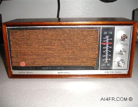
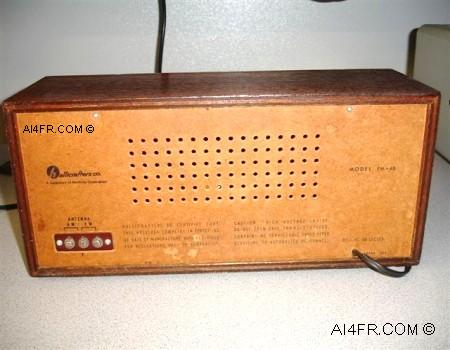
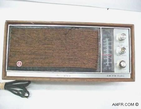
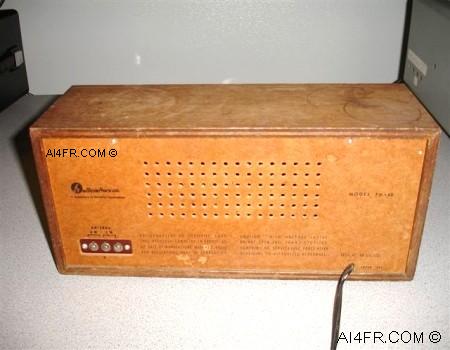
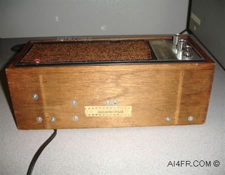
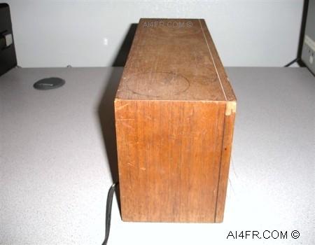
Production Year 1967 at $49.95

The Hallicrafters FM-48 is table top receiver that covers the standard AM and FM broadcast bands. The frequency range for the AM band is 540 KHz to 1600 KHz and for the FM band the radio covers 88 to 108 MHz. This receiver employs 9 transistor and 11 diodes in its circuit. The unit has two I.F. frequencies which are 455 KHz for the AM band and 10.7 MHz for the FM band. 

The features include an FM AFC(Automatic Frequency Control) with on/off switch, a line cord antenna(see below) for FM reception, and a ferrite rod antenna for AM reception. The FM-48 also has provisions on the rear of the unit for external antenna connections for both AM and FM. The AFC has a hold range of around 300 KHz. The front panel controls are as follows, at the top is the Main Tuning control, followed by the AM, FM and FM AFC control in the middle, while the dual knob on the bottom is the ON/FF and volume control knob in the center, while the larger outside knob is a Tone control. The elliptical shaped, 4 inch by 6 inch loudspeaker faces out towards the front of the unit and is of the permanent magnet moving coil design. Received signals exit through a slotted section on the front of the unit. The Pioneer made speaker is rated at 8 ohms and has an audio output rating of 1.5 watts.

The physical dimensions of the FM-48 is 13 1/8 inches wide by 5 1/2 inches tall by 3 1/2 inches deep. The radio requires a 105 to 120 volt AC power source at 60 cycles. The receiver is housed in a wood cabinet that is stained in a Walnut brown color. The receiver sensitivity on AM is 150 uV/M, while on FM it is 5 uV. The AM image rejection is over 25 DB, while on FM it is 37 DB or more. The receiver has an AM selectivity of between 6 to 10 KHz at 6 DB, while the FM intermediate frequency is between 150 to 250 KHz at 6 DB. The Hallicrafters FM-48 was manufactured in Japan.

The Hallicrafters FM-48 is identical to the Hallicrafters FM-46 except the FM-46 is housed in a plastic cabinet. The FM-48 is nearly identical to both the Hallicrafters FM-52 and Hallicrafters FM-54 receivers. The difference being is that the FM-52 and FM-54 have the addition of an electronic clock and its associated components. The FM-52 is also housed in a plastic cabinet, while the FM-54 is housed in wood.

Here is an interesting thought, In 1967 the Hallicrafters FM-48 would have cost the consumer $50. Can you imagine buying a simple AM/FM radio for that amount of money today? The value of $50 back then is equal to roughly $327.57 today?

The picture on the left is of the front of the receiver. The brown grill cloth on the front should cover all of the black area around its edges. I did not replace this cloth, instead opting in this case to leave it alone after I had secured it back in place.

The photograph on the right is of the back of the receiver. There is only one connection that is found on the back of the unit which is on the bottom left hand corner. This connection is used for improving reception by adding an external antenna and consists of a 3 terminal antenna strip  The screw connection on the left of this antenna strip is for the AM antenna, the one at the right is for the FM antenna, while the center screw is for the ground connection. Text printed on the back cover of the receiver identifies the model as FM-48. Printed on the bottom edge of the back cover is two sets of text. The text on the left reads as follows "Hallicrafters Co. certifies that this receiver complies in effect as of the date of manufacture with FCC rules and regulations part 15 subpart C.". The text on the right reads as follows, "Caution: high voltage inside. Do not open case. Transistorized. Contains no serviceable parts. Refer servicing to authorized personnel.".  

Both of the above photographs were taken after I had completed the restoration of this receiver. The pictures at the bottom of this web page show the condition of the receiver when it first arrived. This was a rather simple one to restore that required very little electronic trouble shooting to bring it to full operating condition. The refinishing of the wood cabinet took the greatest amount of time.


The photograph on the left is of the side of the Hallicrafters FM-48. Both the left and right side of this receiver look about the same. Neither side has any control knobs or switches of any kind.  

The picture on the right is of the bottom of the receiver. When I first received the radio it had no feet or legs on it whatsoever. From what I could tell, the original feet were nailed to the bottom. All that remained of them was the nails which were removed and replaced with the round felt stick-on feet as seen in the picture. The rectangular paper sticker is from Hallicrafters and has the serial number of the receiver printed on it. Another identical paper sticker was found on the inside of the cabinet. Normally with Hallicrafters receivers, I find that there is only one serial number sticker which is usually found located on either the bottom or on the back panel.  


These next two photographs are a view looking inside the FM-48 with the back panel removed. In short, this receiver with its modern components is a far cry from the hefty Hallicrafters receivers from yesteryear.

The picture at the left is of the left side of the receiver. In the top corner an air variable capacitor is found which is used for tuning in stations. In the bottom left hand corner of the picture, the external antenna connection can be seen which consists of a 3 terminal antenna strip  The screw connection on the left of this antenna strip is for the AM antenna, the one at the right is for the FM antenna, while the center screw is for the ground connection. 

The photograph on the right is of the right side of the receiver. In this picture, the AM ferrite rod antenna can be seen mounted above the speaker and near the roof. The FM line cord antenna can also be seen in the lower right hand corner and directly in front of the power supply transformer.  

So what exactly is an FM line cord antenna?

The red arrow in the picture on the left is pointing to the FM line cord antenna as installed on the AC power cord from the factory. The red arrow in the photograph on the right is pointing to the same FM line cord antenna now disconnected from the power cord. The inside of the FM line cord antenna can also be seen in this picture.

The FM line cord antenna does not actually make physical contact with the current carrying wires of the power cord, but rather couples to them. The white FM antenna wire lead is soldered to the U shaped piece of metal which is then wrapped around the power cord. That's all there is to the construction of a line cord antenna. Some installations will be found with turns of wire rather then the solid bar of metal that is shown above. The FM line cord antenna is normally not found on portable radios. The location of the power cord will affect the performance of the FM line cord antenna. An annoyance of this type of antenna system is that it is some times necessary to shift the position of the power cord for better reception, especially when you wish to listen to another radio station. During the normal day-to-day house cleaning, the position of the power cord could easily change as well and thus forcing the listener to make adjustments. Even though the antenna is wrapped around the power cord, there is usually no danger of an electrical shock to the operator as long as the power cord is in good condition.

At my home which is near a some what large city, I have found that both the FM line cord antenna and the AM ferrite rod antenna do an excellent job of pulling in signals and no further antennas are necessary. If this is not the case in your area, there are some tricks that may help the performance of the FM line cord antenna. The FM line cord antenna can be improved upon at times by swapping or flipping the way the power cord is plugged into the wall. If this does not help, try changing the position of the power cord so that it is broadside to the radio station you wish to receive and be sure that the power cord is stretched out to its full length. If all this fails, then the external antenna connections should be used. A small length of wire just a few feet long and connected to the external antenna connection can often out preform most FM line cord antennas. Adding an extension cord to the receiver will not help the FM line cord antenna.  

These two photographs show the Hallicrafters FM-48 in the condition that it was received. The picture on the left is of the front of the receiver. Some of the dirt and grime as well as a spider web can be seen through the clear plastic that is covering the frequency display. In this condition it was difficult to even see the slide rule pointer for operation. The picture on the right is of the back of the receiver. Notice the cup stains and worn finish on the top of the wood cabinet.


These last two photographs show the Hallicrafters FM-48 in the condition that it was received. The picture on the left is of the bottom of the receiver. The picture on the right is of the left side of the receiver. A coffee cup stain is easily ascertainable on the top of the cabinet.


Resources:

Radios by Hallicrafters with Price Guide by Chuck Dachis

Hallicrafters owners manual

Sam's photofacts by Howard W. Sams & Co., Inc.  

      AI4FR                                                                                                                                                                                                  AI4FR                                                                                                       AI4FR

Trump WON!! Biden CHEATED!!

Avoid the experimental gene therapy C19 DEATH shot!!  

Think Critically!!

Ukraine = Corruption

Was Hitler right?

Copyright © John Whitt 2022 All rights reserved. 

Created with the QTH.com SiteBuilder.