AI4FR Virtual Shack Tour 

Hallicrafters Items


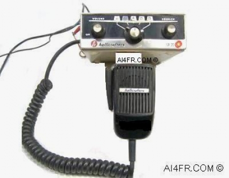
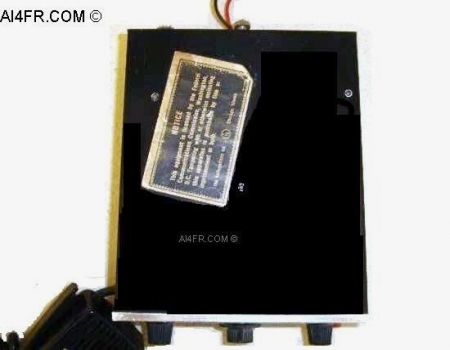
Production Year 1966 at $99.95 

The Hallicrafters model CB-20 Citizen Band transceiver is a compact, crystal controlled, completely transistorized transceiver that provides up to five channels of operation in the class D citizen band service. The CB-20 incorporates a three stage, transistorized transmitter that is capable of the full Federal Communication Commission(FCC) authorized power limit of 5 watts along with a high level of modulation capabilities. The unit contains a completely transistorized superheterodyne receiver using single conversion. The unit also employs a series type noise limiter to reduce automobile and other local interference. It has an electronic Push-To-Talk(PTT), a high capacity ceramic microphone and a self contained speaker. The CB-20 has 12 transistors, 9 diodes. and one Zener diode voltage regulator.

From the factory, the CB-20 is only supplied for operation on channel 11. Although it is possible for the transceiver to operate on any of the lower 23 channels of the citizen band. In order for it to do so, the unit will need to be disassembled and have additional transmitting and receiving CR-81/U type crystals installed into the provided crystal sockets for the desired frequencies. The CB-20 allows for operation on any five of the lower 23 frequencies or channels of the citizen band. Should crystals be added or replaced for operation on the citizen band channels 1 through 23, no transmitter adjustments should be required. The FCC requires, however, that after the installation of new crystals, the transmitter by checked by a person holding a 1st or 2nd class commercial operators license. The loudspeaker which faces out towards the bottom of the unit is of the permanent magnet moving coil design. Received signals exit through a slotted section on the bottom of the unit. The speaker has an audio output rating of 2 watts. The entire transceiver is housed in a sturdy metal cabinet.

The front panel controls are as follows; starting from the left, an On/Off plus Volume control knob, Channel selector knob, and on the right is a Squelch control. The transmitter section is rated at 5 watts input and has a frequency range of 26.965 MHz to 27.255 MHz. The transmitter has been designed to operate into a 50 ohm load. A Television Interference(TVI) circuit has been incorporated into the transceiver which consists of a bandpass matching network with a 50 DB minimum. The receiver has a sensitivity of less than one microvolt for a 10DB signal and noise to noise ratio.

This transceiver requires a 12 volts negative ground DC power source. When the unit is operated in the receive mode with the squelch open, it draws 3/4 of an amp. When the squelch is applied and there is no sound coming from the speaker in the receive mode, the power consumption drops to 0.07 of an amp. During transmit with maximum modulation the unit draws 1.3 amps.

The physical dimensions are 8 1/2 inches long by 6 inches wide by 2 3/8 inches tall. In the box along with the CB-20 was a mounting bracket, and a separate envelope containing the following items, an FCC license application form 505, an FCC transmitter identification card, a warranty registration card, microphone holder, bracket mounting screws, red lead with fuse holder, black lead, and a perforated rear mounting strap. Optional accessories for the CB-20 included an AC to DC base station power supply and a HA-3 electrical noise suppression kit which eliminated noise that was generated by the automobile that the CB-20 was installed in.

The photograph on the left is a picture of the face of the CB-20. Across the front of the ceramic microphone is a metal sticker with the Hallicrafters name on it. The microphone should be held about one or two inches away from the operators mouth when transmitting. The coiled microphone cable has been wired directly to the circuit board. The CB-20 has been designed with no microphone connector on the outside of the case, thus making the switch to a different microphone an involved task. This was done because of the electronic switching used in the transceiver. Hallicrafters states that it is imperative that only the microphone that was supplied with the unit be used. The electronic switching sequence is as follows; the red and black leads must short before, or at the same instant, but never after the microphone circuit is completed by activation of the PTT switch. Conversely, upon deactivation of the PTT switch, the microphone circuit must open first.

The picture on the right is of the top of the unit. The paper Hallicrafters sticker found here reads as follows....

"NOTICE This equipment is licensed by the Federal Communication Commission, Washington D.C. Tampering with or otherwise molesting this apparatus is punishable by fine or imprisonment or both. The Hallicrafters Company Chicago Illinois".  

The photograph on the left is of the right side of the transceiver showing a user applied sticker that was supplied with the CB-20. The sticker is from Hallicrafters and has their logo on each upper corner. The sticker states that it is a "Transmitter Identification Card" and has a spot for the station call sign which happens to be "KJU 8284", and a spot for the station address. In the instruction manual it informs the owner to fill out this transmitter identification card and then attach it to the side of the CB-20. The station call sign was issued by the FCC at a time when such call signs were required to operate on the citizen band(CB). Today, a license to operate a CB radio is no longer required.

The principal requirements for operating a CB back then were found under Part 95 of the FCC Rules and Regulations. These operating rules included such things as; "You must call another person by their license number, and identify yourself by your own.". Another rule stated that you can only transmit for 5 minutes, then you must wait for 5 minutes before making another call. Yet another rule stated that you could not use the CB to sell any thing, nor could you charge a fee to any one for using CB. A rather interesting regulation of Part 95 stated that you may not use your radio for merely "passing the time of day", in other words, you should have a definite purpose for making the call. You also had to be over 18 years old. Lastly, if you wanted to talk with friends or associates who have their own equipment under their own license, such communications must be conducted only on 7 channels, 9 through 14 and channel 23. All of the remaining 16 channels are reserved for communications between stations of the same license. That meant that the remaining 16 channels were used to talk with folks in your immediate family or whom were connected with your business that you have given permission to use your equipment. In order to receive the license, you were required to fill out form 505 and forward it along with the associated license fee to the FCC office in Gettysburg, Pennsylvania. The form 505 was included with the CB-20 or a person could acquire one at any FCC office. It normally took the FCC around 3 to 8 weeks to process your application.

The picture on the right is of the back panel of the transceiver. Moving from right to left on the back panel we find a connection for a 50 ohm coax transmission line, a ground connection, power supply cables that extend out the back of the unit underneath the ground, and lastly, on the left is a transistor which is using the sheet metal back panel as a heat sink.


The photograph on the left is a view of the bottom panel of the Hallicrafters CB-20. In the lower right hand corner of the bottom panel is found two pre-drilled holes for the microphone clip. Also in this picture we can see the slotted section on the bottom panel where the audio from the speaker exits the transceiver. As mentioned in the text at the top of the page, the CB-20 employs electronic switching rather than using relays. This is an important factor to keep in mind when servicing the transceiver. The reason being is that the electronic switching puts the speaker leads at a positive potential above ground and equal to the source voltage. This means that the DC isolation of the common ground associated with some types of test equipment, may be necessary when the speaker leads are terminated by such test equipment.  

The photograph on the right displays the circuit board and internal components of the CB-20. In the upper right corner of this picture can be seen the red crystal sockets and the bank of only six crystals. As you may have surmised from this picture while doing a little math, two additional channels which total 4 crystals could still be added. The crystals are of the CR-81/U series resonant, third over-tone type and should have a tolerance of at least 0.002%. The crystal frequency is the same for both the transmitter and the receiver, except that the receiving crystals should be 455 KC lower in frequency. The Hallicrafters part number for the receiving crystals is 19-3939-(channel number) such as 19-3939-5 for channel 5. The Hallicrafters part number for the transmitting crystals is 19-3484-(channel number) such as 19-3484-2 for channel 2. Preceding these numbers should be the capital letter T or R. The letter T indicates that the crystal is to be installed in the transmitting crystal socket, while the letter R indicates that the crystal should be installed in the receiving crystal socket.


Resources:

Radios by Hallicrafters with Price Guide by Chuck Dachis

Hallicrafters owners manual

Sam's photofacts by Howard W. Sams & Co., Inc.

      AI4FR                                                                                                                                                                                                  AI4FR                                                                                                       AI4FR

Trump WON!! Biden CHEATED!!

Avoid the experimental gene therapy C19 DEATH shot!!  

Think Critically!!

Ukraine = Corruption

Was Hitler right?

Copyright © John Whitt 2022 All rights reserved. 

Created with the QTH.com SiteBuilder.