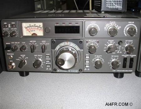
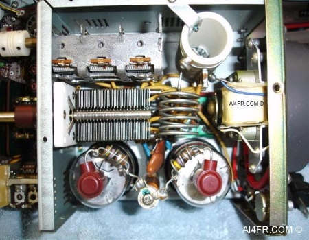
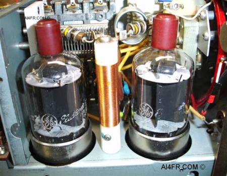
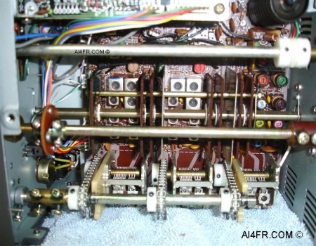
The Kenwood TS-530S is the next generation of Kenwood hybrids(solid state/tube) following the TS-520S. It is designed for SSB and CW modes in the 160 through 10 meter ham bands and from 10.1 through 10.15 MHz (10.0 MHz WWV) in the 30 meter band. This popular 1980's era transceiver employed a single conversion super-heterodyne receiver that was quieter then the dual conversion of that of it's predecessor the TS-520. This transceiver employs a conventional VFO, but uses a Phase Locked Loop(PLL) circuit in the local oscillator. The IF is 8.83 MHz. Some of the main features include a RF attenuation, selectable filters, RIT, variable level noise blanker, selectable AGC and IF shift. I should point out that the selectable filter feature only applies if any optional filters have been installed. The transmitter has a VOX, XIT, speech processor and variable carrier level(CW only) circuitry. The final amplifier uses 3 tubes, a 12BY7A as the driver and two 6146B's. This combination produced a power input of 220W PEP on SSB and 180W DC on CW. The built-in power supply requirements is 120VAC or 220VAC or 240VAC at 50/60 Hz and the power consumed is 295 watts on transmit and 27 watts on receive with the heater off. From the factory the TS-530 had the WARC bands circuit installed but transmitting there was disabled due to the fact that these bands were not as of yet allocated for amateur use when this transceiver went to market. The designers at Kenwood knew how to make this an easy fix for the average ham though, not to mention what it could also do for sales. When the WARC bands did finally became available, transmitting in these bands was made possible after simply removing two diodes. Many amateur simply cut one lead of the diodes and left them in place. The size of this transceiver is 13.1/4" wide by 5 1/4" high by 13 1/4" deep and weighs in at just over 28 pounds. |